
Exact product identification
Your quotation references the complete manufacturer part number to keep the requested product clear.
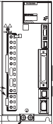
SGD7S-3R8A00A
200 V-class Sigma-7 single-axis analog/pulse SERVOPACK, 0.5 kW maximum applicable motor capacity. 3.8 A rms continuous / 11 A rms instantaneous output; standard three-phase main input, IP20, 70 mm-wide base-mounted frame.
Warranty coverage and terms are confirmed with your order.
We coordinate the fastest available shipping option for your destination.
Available payment methods are handled through secure payment channels.
Carrier and delivery options are confirmed for your destination before dispatch.
Independent supplier: Xindustra is not an authorized distributor, reseller, or representative of Yaskawa. Brand names are used for identification and compatibility purposes only. Read disclaimer
Motor capacity, analog/pulse integration and standard-frame installation for SGD7S-3R8A00A.
SGD7S-3R8A00A is a Sigma-7 SGD7S SERVOPACK with an analog-voltage/pulse-train reference interface and a maximum applicable motor capacity of 0.5 kW. It supplies 3.8 A rms continuously and 11 A rms instantaneously. The instantaneous value is not a continuous operating current or a fixed-duration overload allowance.
SGD7S-3R8A00A
Sigma-7 SGD7S / single axis
Analog voltage / pulse train
200 V AC
0.5 kW
3.8 A rms
11 A rms
A, standard base model
200–240 V AC, three-phase, 50/60 Hz
3 A rms
1.3 kVA
50.5 W
This standard model uses three-phase main power. It is not one of the smaller SGD7S models documented for conversion to single-phase input with Pn00B.
200–240 V AC, single-phase, 50/60 Hz
−15% to +10%
Applies to the stated main and control AC supply ratings.
0.2 A rms
Use a manufacturer-supported SERVOPACK/motor combination with matching voltage, encoder interface, continuous duty and peak demand. A motor with the same kW rating is not automatically a compatible servo axis. Motor power, encoder, brake and I/O cables are selected separately.
The 00 interface code identifies analog-voltage/pulse-train references. Use analog references for speed/torque control or pulse commands for position control with the appropriate mode and input settings. This base model does not have the MECHATROLINK, EtherCAT or PROFINET command interface of other SGD7S order codes.
Host I/O and command signals
Reference pulse input, reference voltage, sequence I/O and divided encoder pulse output.
Servomotor encoder / feedback
Digital Operator / RS-422A service communication
Analog monitor output
USB connection to a computer running SigmaWin+
Safety-function signal connection
SigmaWin+ connects through the service interface for parameter setup, monitoring and tuning. It does not turn USB into the machine’s real-time motion-command network. Keep command wiring, encoder feedback and motor power on their designated connections.
The standard A00A code does not specify a separately installed feedback, advanced-safety or controller option module. Those functions require the matching option and its own wiring/configuration; do not infer them from general Sigma-7 family marketing.
40 W nominal resistor capacity
40 Ω
40 Ω
This is the minimum resistance limit, not the required resistor wattage for every machine.
This model has a built-in regenerative resistor, but repeated deceleration or an overhauling load can require an external resistor sized for the actual energy and duty cycle. The 40 W resistor capacity is not the motor output rating or the total thermal loss of the SERVOPACK.
The product manual gives the regeneration terminal arrangement for each frame. When replacing a built-in resistor with an external one, remove the specified B2–B3 link and connect the external resistor between B1/+ and B2 as directed for that model. Dynamic braking and a motor holding brake perform different stopping/holding roles; neither is a substitute for correctly sizing regenerative energy.
70 × 168 × 180 mm
1.6 kg
Base-mounted, upright on a vertical mounting surface
3 × M4
IP20
−5 to +55 °C
55–60 °C operation requires manufacturer derating.
−20 to +85 °C
≤95%, without freezing or condensation
Up to 1,000 m
1,000–2,000 m requires manufacturer derating.
Housing and mounting dimensions
Original manufacturer drawing for the 3R8A standard base-mounted frame. Dimensions in millimetres; connected-cable space and mounting pitch are shown separately from body depth.
For an individually installed SERVOPACK, reserve at least 40 mm above/below and 30 mm on each side as shown in the manual. For grouped units, the documented right-side gap for this frame is 1 mm with at least 0.5 m/s fan airflow measured 10 mm above the top surface; grouping is not a blanket permission to eliminate ventilation. Connected cables need additional front clearance.
IP20 is the SERVOPACK enclosure rating, not an outdoor or washdown rating. Keep water, oil, conductive dust and corrosive gases away from the unit. The body dimensions exclude the connected-cable envelope shown in the original drawing.
Manufacturer model selection, engineering details and setup references.
Order the exact product and condition your project requires, with assistance from quotation through delivery.
Your quotation references the complete manufacturer part number to keep the requested product clear.
Tell us whether you need new original, new surplus, used, refurbished or repaired equipment.
Shipping options are prepared around your destination, quantity and requested delivery date.
Access available manufacturer product data, manuals and certificates associated with the order number.