
Exact product identification
Your quotation references the complete manufacturer part number to keep the requested product clear.
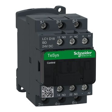
LC1D18BD
TeSys Deca 3-pole nonreversing contactor, 18 A AC-3/AC-3e at ≤440 V AC, 7.5 kW at 380/400 V. 24 V DC standard coil, 3 NO main poles and 1 NO + 1 NC auxiliaries; 45 mm-wide body.
Warranty coverage and terms are confirmed with your order.
We coordinate the fastest available shipping option for your destination.
Available payment methods are handled through secure payment channels.
Carrier and delivery options are confirmed for your destination before dispatch.
Independent supplier: Xindustra is not an authorized distributor, reseller, or representative of Schneider Electric. Brand names are used for identification and compatibility purposes only. Read disclaimer
Motor-duty ratings, coil supply, terminals and installed dimensions for LC1D18BD.
LC1D18BD is a TeSys Deca nonreversing contactor with three normally open main poles and one NO plus one NC built-in auxiliary contact. Its motor-duty rating is 18 A AC-3/AC-3e at up to 440 V AC and below 60 °C. It switches the motor power circuit when the separate 24 V DC coil is energized; it is not a motor drive, overload relay or circuit breaker.
LC1D18BD
3P / 3 NO
1 NO + 1 NC
24 V DC, standard DC coil
18 A at ≤440 V AC, <60 °C
32 A at ≤440 V AC, <60 °C
7.5 kW, AC-3
Nonreversing, open style
| Parameter / condition | AC-3 motor power |
|---|---|
| 220/230 V | 4 kW |
| 380/400 V | 7.5 kW |
| 415 V | 9 kW |
Three-phase AC motor ratings at 50/60 Hz. The coil is separately rated 24 V DC; these voltages describe the switched motor circuit.
The 32 A AC-1 value describes resistive-load duty; it is not the motor-duty rating. AC-3 covers normal starting and stopping of a running motor, while inching, plugging and frequent reversing use different AC-4 conditions. AC-3e addresses the corresponding high-efficiency motor duty. Select from the published duty and supply voltage rather than applying one current or kW value to every load.
The BD suffix identifies the 24 V DC coil configuration. It does not limit the motor supply to 24 V, and a 24 V AC coil is a different order number. The 400 V motor kW figure is not a coil rating.
Standard DC
24 V DC
5.4 W at 20 °C
5.4 W at 20 °C
0.7–1.25 Uc at −40 to +60 °C
1–1.25 Uc at +60 to +70 °C
Integral suppression device
The control circuit must support the 5.4 W pickup demand and 5.4 W holding demand at the stated reference temperature. A 24 V output’s nominal voltage alone does not establish that it can drive this coil directly. Use a suitably rated output or interposing device, and include switching transients and the output manufacturer’s load requirements.
This exact DC-coil model includes an integral suppression device. It is not the low-consumption BL coil or the newer wide-range BNE control option; those have different full references and electrical characteristics.
The built-in 1 NO and 1 NC contacts are separate from the three main power poles. Use their own published control-circuit ratings for feedback, seal-in or interlocking. They are not extra motor-power poles, and mechanically linked/mirror-contact construction does not by itself make the contactor a complete safety-control system.
A1 / A2; observe the markings on the exact unit
1/L1, 3/L2, 5/L3
2/T1, 4/T2, 6/T3
13–14
21–22
Screw clamp terminals
1.7 N·m
1.7 N·m
Exact product data sheet, wiring section. The dashed linkage is mechanical operation; main and auxiliary contacts are distinct circuits.
Use the conductor count, cross-section, ferrule arrangement and tool specified for each power or control terminal. The higher-current EverLink power connection has different torque requirements from the control screws; do not apply one tightening torque to every terminal.
Provide overload and short-circuit protection appropriate to the motor branch. Any high short-circuit rating belongs to the tested combination of contactor and specified protective devices at the specified voltage. It is not the contactor’s independent breaking capacity and does not turn it into a circuit breaker.
This is one nonreversing contactor. A reversing starter uses an appropriate paired arrangement, electrical and mechanical interlocking and coordinated protection; a single LC1D order number is not a complete reversing assembly.
45 × 77 × 95 mm
0.49 kg
Rail or plate
IP20, front face
−40 to +60 °C
+60 to +70 °C with derating
Up to 3000 m
Exact product data sheet, dimensions section. Lettered dimensions and accessory rows describe different installed configurations; add-on blocks are not included merely because they appear in the drawing.
The stated 45 × 77 × 95 mm envelope does not include every possible overload relay, auxiliary block, timer, interlock or cable bend. Use the original dimensional table for the selected accessories and retain the marked electrical clearance. IP20 at the front is not an outdoor enclosure rating.
Above 60 °C, load derating applies and the coil supply window changes to 1–1.25 Uc. The +70 °C upper ambient value is not an unconditional full-load rating.
Order the exact product and condition your project requires, with assistance from quotation through delivery.
Your quotation references the complete manufacturer part number to keep the requested product clear.
Tell us whether you need new original, new surplus, used, refurbished or repaired equipment.
Shipping options are prepared around your destination, quantity and requested delivery date.
Access available manufacturer product data, manuals and certificates associated with the order number.