
Exact product identification
Your quotation references the complete manufacturer part number to keep the requested product clear.
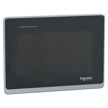
HMIST6400
Harmony ST6 Basic HMI with 7-inch 800 × 480 color resistive touchscreen, 2 Ethernet and 2 serial ports, USB host/transfer and 24 V DC supply. 190 × 135 mm panel opening; EcoStruxure Operator Terminal Expert engineering.
Warranty coverage and terms are confirmed with your order.
We coordinate the fastest available shipping option for your destination.
Available payment methods are handled through secure payment channels.
Carrier and delivery options are confirmed for your destination before dispatch.
Independent supplier: Xindustra is not an authorized distributor, reseller, or representative of Schneider Electric. Brand names are used for identification and compatibility purposes only. Read disclaimer
Display, communications, cabinet fit and operating requirements for HMIST6400.
HMIST6400 is a complete Harmony ST6 Basic HMI for machine visualization and operator input, with a 7-inch wide color display at 800 × 480 pixels. It runs an HMI project created with EcoStruxure Operator Terminal Expert and connects to the machine controller through two Ethernet ports and separate RS-232C and RS-485 serial ports. This is the standard integrated Basic panel, rather than an STW6 web terminal or STM6 modular display.
HMIST6400
Harmony ST6 / Basic HMI
7 inches, wide
TFT color LCD
800 × 480 pixels
16 million
Analog resistive, single touch
16 levels
White LED
50,000 hours or more
Continuous operation at 25 °C, until brightness decreases to 25%.
1 million operations or more
The resistive touch panel accepts one touch at a time. Two simultaneous touches can be interpreted at their midpoint, so screens should use deliberate single-touch controls rather than multi-finger gestures. The LCD pixel resolution describes the visible layout; it is separate from the touch sensor coordinate resolution.
ARM Cortex-A8
1 GB Flash EPROM
128 MB
512 KB NVRAM
200
EcoStruxure Operator Terminal Expert
Built-in real-time clock with primary battery backup
Create the screens, tags, alarms and controller connections in EcoStruxure Operator Terminal Expert, then transfer the project to the HMI. Schneider’s Basic-license compatibility FAQ includes all five standard HMIST6 models. The panel is not a general-purpose PC or a web-only browser terminal; the software license and engineering workstation are separate from this hardware order number.
2 × RJ45, 10BASE-T / 100BASE-TX
D-Sub 9-pin plug; RS-232C
RJ45; RS-485
2,400–115,200 bit/s
Up to 187,500 bit/s
Via COM2 and the appropriate driver.
1 × USB 2.0 Type A; 5 V DC, 500 mA maximum
1 × USB 2.0 micro-B
5 m maximum
Serial interface is not isolated
The two Ethernet sockets and RJ45 serial COM2 are different interfaces. COM1 uses a D-Sub plug for RS-232C; COM2 uses RJ45 for RS-485. An Ethernet patch cable is not a substitute for a serial device cable just because both use RJ45 connectors.
RD / RXD and SD / TXD
Signal ground
RTS / CTS
+5 V DC output, 0.25 A maximum
Enable VCC in software when using pin 9.
Line A (+) / Line B (−)
RTS
Signal ground
No connection
Frame ground
The manufacturer lists Modbus, Uni-TE and third-party controller protocols. Select the exact controller driver, serial electrical mode or Ethernet connection in the HMI project, along with addressing and cable pinout. A manufacturer name in the supported-brand list does not make every controller or communication option interchangeable.
Power the HMI from its DC power connector before connecting the micro-B transfer cable to the engineering computer. USB is a transfer interface, not the panel’s operating power source. Remove the micro-B cable before normal communication with the machine controller, as directed by the user manual.
208 × 153 × 45 mm
190 × 135 mm
+1 / −0 mm on width and height
Less than R3
1.6–5 mm
0.8 kg or less
4
0.5 N·m
At least 100 mm from adjacent structures/equipment
30° from vertical
Original HMIST6400 data sheet, p.6. Body dimensions are not the panel cutout; the drawing includes the front bezel and projection.
The panel opening is 190 × 135 mm; the 208 × 153 mm front bezel overlaps that opening. The listed 45 mm body depth does not include connector bodies or cable bends. Leave the specified service and ventilation clearance behind and around the panel.
The data sheet lists IP65 at the front and IP20 at the rear. The manual specifies IP65F and Type 1/4X/13 front protection when properly installed in a suitable enclosure, with Type 4X for indoor use. Fit the supplied gasket against a flat, rigid surface; the rear housing does not provide a complete machine enclosure.
For portrait mounting, install the panel with its right side upward, placing the DC power connector at the top, and use a project layout that supports portrait operation. Keep ventilation slots clear and account for the cabinet’s internal temperature.
24 V DC
19.2–28.8 V DC
9 W
30 A
5 ms or less at rated voltage
+24 V / 0 V / FG
XBTZGPWS1 type; supplied with panel
0.56 N·m
0–50 °C
−20 to +60 °C
10–90%, non-condensing
Wet-bulb temperature 39 °C or lower.
2,000 m or lower
Natural air circulation
The maximum 9 W consumption includes the panel’s permitted external-device loading; the 30 A inrush is a brief startup demand rather than steady current. Use an external SELV and limited-energy DC source, connect FG to ground, and include a means of disconnecting power because the HMI has no integral power switch.
Keep the unit indoors and out of direct sunlight. Clean the screen with a soft cloth, without pressing with a hard or pointed object. Inspect the installation gasket and replace it at least annually or sooner if damaged or dirty. The white LED backlight is not a user-replaceable lamp; the primary clock battery is a separate service item.
| Parameter / condition | HMIST6200 | HMIST6400 | HMIST6500 | HMIST6600 | HMIST6700 |
|---|---|---|---|---|---|
| Display diagonal | 4.3 in | 7 in | 10.1 in | 12.1 in | 15.6 in |
| LCD pixels | 480 × 272 | 800 × 480 | 1024 × 600 | 1280 × 800 | 1366 × 768 |
| Ethernet / serial ports | 1 / 1 | 2 / 2 | 2 / 2 | 2 / 2 | 2 / 2 |
| Panel opening, mm | 118.5 × 92.5 | 190 × 135 | 255 × 185 | 295 × 217 | 394 × 250 |
All five use 24 V DC and single-touch resistive panels. A larger display also needs a different cabinet opening and HMI project layout.
Order the exact product and condition your project requires, with assistance from quotation through delivery.
Your quotation references the complete manufacturer part number to keep the requested product clear.
Tell us whether you need new original, new surplus, used, refurbished or repaired equipment.
Shipping options are prepared around your destination, quantity and requested delivery date.
Access available manufacturer product data, manuals and certificates associated with the order number.