
Exact product identification
Your quotation references the complete manufacturer part number to keep the requested product clear.
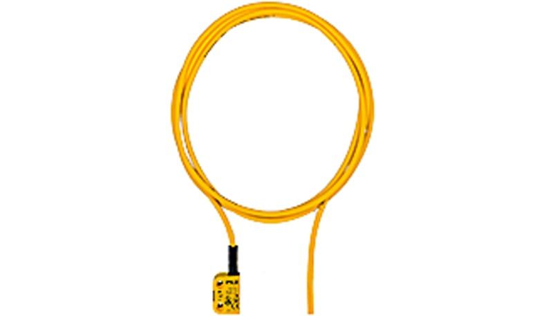
541161
Fully coded compact RFID guard-monitoring switch with 5 m integral cable, 24 V DC and two OSSD outputs. Series-capable with two safety inputs and SDD support. One switch, actuator ordered separately.
Warranty coverage and terms are confirmed with your order.
We coordinate the fastest available shipping option for your destination.
Available payment methods are handled through secure payment channels.
Carrier and delivery options are confirmed for your destination before dispatch.
Independent supplier: Xindustra is not an authorized distributor, reseller, or representative of Pilz. Brand names are used for identification and compatibility purposes only. Read disclaimer
Coding, actuator distances, electrical connections and installation data for 541161.
541161 (PSEN cs4.1a) is a compact non-contact safety switch for monitoring a movable guard using an approved RFID actuator. This order supplies one switch body without the actuator. It detects the guard position; it does not provide guard locking or hold a door closed.
541161
PSEN cs4.1a 1switch
RFID transponder, non-contact
Type 4
Fully coded
High
5 m integral cable
One switch; actuator not included
The first approved actuator is learned automatically when introduced into the response range. A replacement actuator requires the documented teach-in sequence; a maximum of eight learning procedures is possible. This fully coded version is not the separately offered uniquely fully coded variant.
8 mm
11 mm
20 mm
14 mm
One
Switch and actuator face each other in parallel
Values apply to the named standard actuator; other approved actuator shapes have different distances.
The standard compact PSEN cs4.1 actuator is order number 541180. Mount it on the moving guard opposite the fixed switch. The 8 mm assured operating distance and 20 mm assured release distance above refer to that actuator, not every transponder in the PSENcode range.
24 V DC
−20% / +20%
19.2–28.8 V DC.
1 W
20 mA
2 OSSD semiconductor outputs
100 mA maximum
450 µs
2, at 24 V DC
Supported via S11 / S21
S21 — safety input, channel 2
A1 — +24 V DC
12 — OSSD output, channel 1
22 — OSSD output, channel 2
Y32 — signal / diagnostic output
S11 — safety input, channel 1
A2 — 0 V
Y1 — diagnostics input
S11 and S21 receive the two upstream safety signals. For an individual switch, the manufacturer single-connection diagram supplies both inputs from 24 V; in a chain they receive the preceding switch’s two OSSD signals. Outputs 12 and 22 feed the next switch or a two-channel safety evaluation device. Y32 is a status/diagnostic signal, not a third safety channel.
Important fit check
Connect Y32 to a suitable control-system input or leave it open. Do not connect it directly to 0 V: the manufacturer identifies a risk of damaging the switch.
Use a SELV/PELV supply with protective electrical separation, overvoltage protection at or below 35 V DC, and a 2–4 A quick-acting supply fuse. Isolate the supply before connecting or disconnecting the switch.
When the approved actuator moves beyond the assured release distance or is no longer detected, both OSSD outputs switch off. Evaluate both channels with plausibility monitoring; the switch is not a general-purpose single-channel door sensor.
3 Hz
1 s
60 ms typical / 150 ms maximum
40 ms typical / 260 ms maximum
260 ms
15 ms typical / 20 ms maximum
Additional chain-input path; do not replace actuator risk time with this smaller figure.
PL e, Category 4 / SIL CL 3
With an approved actuator and two-channel processing; the complete safety function requires its own assessment.
20 years
Power/Fault indicates readiness or a fault; Safety Gate indicates an actuator within range; Input indicates both safety inputs are high. Safety Device Diagnostics is supported through Y32/Y1 with separately selected SDD equipment. SDD is an additional diagnostic path, not a substitute for the two-channel safety evaluation.
37 × 26 × 18 mm
Manufacturer technical-table nominal dimensions; the detailed drawing gives 26.4 mm width.
PBT
205 g
Device weight, not packed shipping weight.
IP6K9K
−25 to +70 °C
+70 °C below 2000 m; the manufacturer specifies +60 °C at the maximum 4000 m altitude.
100 mm
0.8 N·m
5 m
Li9Y11Y, 8 × 0.14 mm²
5.55 mm
Original PSEN cs4.1a/b drawing, dimensions in millimetres. Switch body geometry is shared by the 5 m cable version; the drawing does not depict the full cable length.
Install the switch and actuator opposite each other in parallel and secure them against movement. Neither component is a mechanical end stop. Keep the specified separation between adjacent switches, and account for the effect of electrically or magnetically conductive mounting materials on the sensing distances.
The 5 m cable has eight conductors for supply, the two safety inputs, the two OSSD outputs and diagnostics. Minimum bending radius is 5 × cable diameter for fixed routing and 10 × diameter for moving routing; support the cable so door movement does not pull on the switch outlet.
Original manufacturer resources for this switch configuration.
Order the exact product and condition your project requires, with assistance from quotation through delivery.
Your quotation references the complete manufacturer part number to keep the requested product clear.
Tell us whether you need new original, new surplus, used, refurbished or repaired equipment.
Shipping options are prepared around your destination, quantity and requested delivery date.
Access available manufacturer product data, manuals and certificates associated with the order number.