
Exact product identification
Your quotation references the complete manufacturer part number to keep the requested product clear.
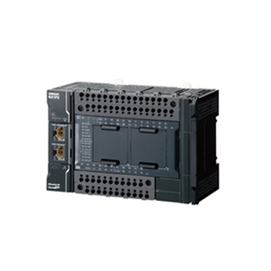
NX1P2-1040DT1
NX1P2 CPU with 24 digital inputs and 16 PNP transistor outputs, 2 motion-control servo axes plus four single-axis positioning axes. Built-in EtherCAT and EtherNet/IP; 24 V DC supply.
Warranty coverage and terms are confirmed with your order.
We coordinate the fastest available shipping option for your destination.
Available payment methods are handled through secure payment channels.
Carrier and delivery options are confirmed for your destination before dispatch.
Independent supplier: Xindustra is not an authorized distributor, reseller, or representative of Omron. Brand names are used for identification and compatibility purposes only. Read disclaimer
Control capacity, PNP I/O wiring, network roles and cabinet requirements for NX1P2-1040DT1.
NX1P2-1040DT1 combines 24 digital inputs and 16 PNP transistor outputs with EtherCAT motion control. Its 6 real servo axes are allocated as 2 motion-control axes and four single-axis positioning axes. Choose this CPU when the machine needs synchronized or coordinated motion as well as independent positioning.
NX1P2-1040DT1
NX-series NX1P2 CPU Units
40 points
6
2
4
1.5 MB
32 kB
2 MB
2 ms
Sysmac Studio
Ladder Diagram, Structured Text and Function Blocks
| Parameter / condition | Motion-control servo axes | Single-axis positioning servo axes |
|---|---|---|
| Available on NX1P2-1040DT1 | 2 | 4 |
| Single-axis positioning | Supported | Supported |
| Single-axis synchronized control | Supported | Not supported |
| Single-axis torque control | Supported | Not supported |
| Multi-axis coordinated control | Supported | Not supported |
The 9024 models have no motion-control servo axes. The 1040 pair provides two; the 1140 pair provides four. All six provide four single-axis positioning axes.
DT1 selects PNP sourcing outputs with load short-circuit protection. Changing between DT and DT1 in the same 9024, 1040 or 1140 class changes the output circuit, not the motion-axis allocation. The 9024 CPU has one option-board slot; 1040 and 1140 CPUs have two.
24
24 V DC (15–28.8 V DC)
Supports NPN or PNP sensor wiring
00–15
16–23
2.5 µs max. ON and OFF
Configured input filtering adds delay.
1 ms max. ON and OFF
Configured input filtering adds delay.
15 V DC min.
5 V DC max. / 1 mA max.
Configured in groups of four points
16
PNP sourcing
24 V DC (15–28.8 V DC)
300 mA
1.8 A
3.6 A per CPU
1 mA
0.1 mA max.
1.5 V max.
0.5 ms max.
1.0 ms max.
Provided at each output point
40 mA per common
Excludes external load current.
The sixteen outputs use two independent common groups. Each common is limited to 1.8 A, and the complete CPU to 3.6 A. Eight simultaneous 300 mA loads in one group would exceed its 1.8 A rating even though each channel is within 300 mA.
00–15
C0 (+V) and C1 (+V) to +24 V; independent groups
0V0 and 0V1 to 0 V; independent internal circuit returns
Leave unconnected
+ / − for CPU supply, functional ground, input COM and numbered inputs
PNP output terminal assignment
Original Omron terminal layout for the 40-point PNP CPU variant. Follow the labeled common and return terminals; NC positions remain unconnected.
Connect output common C0 (+V) and C1 (+V) to the 24 V I/O supply and connect 0V0 / 0V1 to its 0 V return. The load connects between the output and 0 V. DT1 provides load short-circuit protection at each point; channel and common-current ratings still apply.
| Parameter / condition | EtherNet/IP port 1 | EtherCAT port 2 |
|---|---|---|
| Physical connector | One RJ45 | One RJ45 |
| Role | EtherNet/IP data exchange and Ethernet engineering connection | EtherCAT master for field I/O and drives |
| Physical layer | 10BASE-T / 100BASE-TX | 100BASE-TX |
| Maximum node-to-node cable length | 100 m through Ethernet switch | 100 m between EtherCAT nodes |
| Capacity | 32 cyclic tag-data-link connections | 16 EtherCAT slaves |
The two RJ45 connectors serve different network roles; a shared connector shape does not make them interchangeable.
Up to 8
Up to 24
Eight on the CPU rack plus sixteen on EtherCAT slave terminals.
2,000–8,000 µs in 250 µs increments
2
10 W maximum
0.8
Not supplied by the CPU
The CPU can supply up to 10 W of NX unit power for local module electronics. It does not supply NX-bus field I/O power. Local modules that receive field I/O power through the NX bus require an Additional I/O Power Supply Unit; that supply has a maximum 4 A I/O current. Add the local NX electronics load to the external CPU power budget.
NX1P2-1040DT1 has 2 option-board slots. NX1W-CIF01 adds RS-232C; NX1W-CIF11 adds RS-422A/485; NX1W-CIF12 adds isolated RS-422A/485. NX1W analog option boards provide the specified analog input/output functions. These interfaces are separately selected boards, not built-in serial or analog ports.
Select the complete NX1P2 order number, configure the built-in I/O and NX units, map EtherCAT slaves and allocate motion/positioning axes in the project. CPU unit version and project settings govern version-dependent functions; ring topology requires project unit version 1.40 or later and ring-capable slaves.
24 V DC (20.4–28.8 V DC)
6.85 W
Includes SD memory card and option board; excludes power supplied to NX units.
10 A max. for 0.1 ms max.; 2.5 A max. for 150 ms max.
4 A maximum
Non-isolated between CPU power input and internal circuit
Not provided
Not provided
154 × 100 × 71 mm
Includes NX-END02 end cover; excludes projecting parts.
660 g
Includes the end cover.
DIN rail inside a panel
0–55 °C
10–95% RH, no condensation
−25–70 °C
Excludes battery.
2,000 m
Free from corrosive gases
Less than 100 Ω
2 or less
II
40-point CPU front dimensions
Original Omron drawing shows the bare CPU width as 148 mm. The supplied NX-END02 end cover adds 6 mm, giving the 154 mm assembly width used above. Dimensions are in millimetres; projecting features are shown separately.
CPU side profile
Original Omron side-view dimensions in millimetres. Use the 71 mm overall depth and retain space for projecting parts and wiring.
One NX-END02 end cover is provided with the CPU unit. The CJ1W-BAT01 backup battery is sold separately. Install the end cover at the right end of the CPU/NX assembly; it is not an expansion I/O module. Select the SD card, option boards and external power supplies for the machine configuration.
Allow for the listed cold-start inrush and the local NX electronics power demand, in addition to the CPU consumption. Respect the 4 A supply-terminal through-current limit when daisy-chaining power wiring. External actuator loads need their own correctly wired I/O supply circuit.
Omron model information, family data and engineering documentation.
Order the exact product and condition your project requires, with assistance from quotation through delivery.
Your quotation references the complete manufacturer part number to keep the requested product clear.
Tell us whether you need new original, new surplus, used, refurbished or repaired equipment.
Shipping options are prepared around your destination, quantity and requested delivery date.
Access available manufacturer product data, manuals and certificates associated with the order number.