
Exact product identification
Your quotation references the complete manufacturer part number to keep the requested product clear.
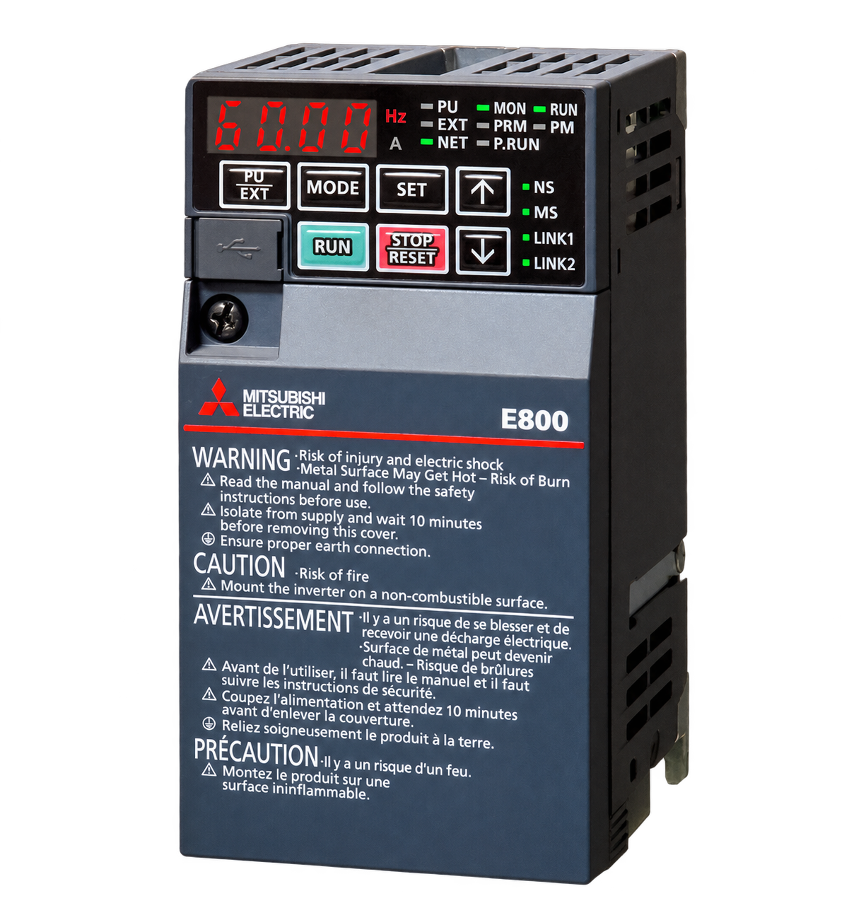
FR-E820-0008-4-60
FR-E800 standard inverter for three-phase 200–240 V: 0.1 kW / 0.8 A ND or 0.2 kW / 1.3 A LD. RS-485, AM monitor output, initial source logic and 50 Hz settings; coated circuit board. No built-in brake transistor.
Warranty coverage and terms are confirmed with your order.
We coordinate the fastest available shipping option for your destination.
Available payment methods are handled through secure payment channels.
Carrier and delivery options are confirmed for your destination before dispatch.
Independent supplier: Xindustra is not an authorized distributor, reseller, or representative of Mitsubishi Electric. Brand names are used for identification and compatibility purposes only. Read disclaimer
Duty ratings, power connections, control logic and panel dimensions for FR-E820-0008-4-60.
FR-E820-0008-4-60 is a standard FR-E800 inverter for a three-phase 200–240 V supply. It provides 0.8 A in normal duty (ND) or 1.3 A in light duty (LD). ND retains the higher overload allowance; LD offers a larger motor-capacity reference with a lower overload allowance. Select the duty using motor rated current and the machine’s acceleration and overload demand.
| Parameter / condition | Normal duty (ND) | Light duty (LD) |
|---|---|---|
| Applicable motor capacity | 0.1 kW | 0.2 kW |
| Rated output current | 0.8 A | 1.3 A |
| Reduced output current at the condition below | 0.8 A | 1.1 A |
| Rated output capacity at 230 V | 0.3 kVA | 0.5 kVA |
| Overload for 60 seconds | 150% | 120% |
| Overload for 3 seconds | 200% | 150% |
Motor-capacity references are for Mitsubishi Electric four-pole standard motors. Reduced-current values apply during low-acoustic-noise operation when surrounding air exceeds 40 °C and Pr.72 PWM frequency selection is 2 kHz or higher. Overload ratings are inverse-time values at 50 °C; allow the inverter and motor to cool before repeating an overload.
Three-phase 200–240 V
Output voltage cannot exceed the supply voltage.
V/F, Advanced magnetic flux vector, Real sensorless vector
Available with FR-A8AP E kit
Separately selected feedback option, not built into the standard drive.
PM sensorless vector
0.2–590 Hz in V/F; up to 400 Hz in vector control
0.2–400 Hz
Do not exceed the connected motor’s maximum operating frequency.
0–3,600 s, set independently
Linear or S-pattern ramp.
Enter the connected motor ratings and select the appropriate control method and duty setting. The higher LD kW figure is not an increase in ND overload capability. A motor requiring the ND overload profile must be sized against the ND current, with the temperature and carrier-frequency conditions above applied.
Three-phase 200–240 V AC, 50/60 Hz
170–264 V AC
±5%
No
None
Optional FR-HEL
Remove the P1–P/+ jumper only when connecting the reactor.
| Parameter / condition | Normal duty (ND) | Light duty (LD) |
|---|---|---|
| Input current, without DC reactor | 1.4 A | 1.9 A |
| Input current, with DC reactor | 0.8 A | 1.3 A |
| Supply capacity, without DC reactor | 0.5 kVA | 0.7 kVA |
| Supply capacity, with DC reactor | 0.3 kVA | 0.5 kVA |
Input figures depend on supply impedance and are not output-current ratings. The reactor figures describe an optional installation, not an included reactor. Use the manufacturer’s switchgear and cable tables for branch protection and conductor selection.
Three-phase AC input
Three-phase motor output
DC-reactor connection
Keep the factory jumper in place if no DC reactor is fitted.
Direct brake-resistor connection unavailable
This model has no built-in brake transistor.
Connection for a separately selected brake unit
Earth the inverter chassis and motor
FR-E820-0008-4-60 does not contain a brake transistor. Do not connect an FR-ABR, MRS or MYS resistor directly across P/+ and PR. Regenerative braking requiring an external energy-dissipation path uses a separately selected brake-unit arrangement, such as FR-BU2 at P/+ and N/−, rather than a resistor-only connection.
Important fit check
The incoming supply connects to R/L1, S/L2 and T/L3, not to U, V and W. Motor leads connect to the output terminals. Protective earth is required; control terminals are not power-input terminals. Isolate the supply and observe the discharge procedure before accessing the main circuit.
The -4 specification is the standard RS-485 model with AM voltage monitoring, initial 50 Hz settings and source input logic. The -60 suffix specifies circuit-board coating without plated conductors; it does not mean a 60 Hz initial setting. This is not the Ethernet or safety-communication version of FR-E800.
7
STF, STR, RH, RM, RL, MRS and RES; assignments selected by Pr.178–184.
Source
2: terminals 2 and 4
0–5 V / 0–10 V / 4–20 mA (0–20 mA), selected by parameter and voltage/current switch.
2: RUN and FU
Assignments selected by Pr.190–191; common SE.
1 changeover contact: A, B, C
Assignment selected by Pr.192.
−10 to +10 V, 12-bit
Common terminal 5; 1 mA maximum load and 10 kΩ minimum load impedance.
Not used on this AM specification
S1 and S2
Two-channel hardwired safety-stop input; a safety relay and the functional-safety wiring arrangement are system-level provisions.
PU connector and USB mini-B
Source-logic contact wiring
Original Mitsubishi Electric source-logic inset. The contact closes between PC and the selected input (RES in this example). The -4 specification starts in source logic; the main family diagram also contains a sink-logic circuit and other specification variants.
Set Pr.73 for terminal 2 and Pr.267 for terminal 4 together with the V/I input switch. A current signal must use the current-input configuration. Terminal 4’s current-input operation uses the AU selection signal; assign AU to a contact input when this control mode is used. Terminal 10 provides the 5 V potentiometer reference, and terminal 5 is analog common.
Mitsubishi inverter protocol, MODBUS RTU, BACnet MS/TP
CC-Link, DeviceNet, PROFIBUS-DPV0
Require the corresponding separately selected communication option.
Not included
Ethernet variants are separate FR-E800-E order configurations.
Select the operating mode, motor data, frequency command source and acceleration/deceleration parameters before applying the run command. The integrated panel supports local operation and monitoring; USB provides a PC engineering connection for FR Configurator2, not an Ethernet network interface.
68 × 128 × 80.5 mm
56 × 118 mm
5 mm
10 mm
108.1 mm
Allow this larger depth when an option is installed.
0.5 kg
Natural convection
IP20
Vertical on a non-combustible panel surface
Front outline and mounting references
Original FR-E820 0.1–0.75 kW outline. For this 0.1 kW ND model: W 68 mm, H 128 mm, W1 56 mm, H1 118 mm and C 5 mm. The manufacturer’s kW drawing designation uses the ND rating.
Side outline and depth references
Original manufacturer outline, dimensions in millimetres. For FR-E820-0008-4-60, D is 80.5 mm and D1 is 10 mm. With the separately fitted plug-in option, D2 increases the required depth to 108.1 mm.
−20 to +60 °C
Reduce rated current above 50 °C; the low-noise/high-carrier current condition above also applies.
95% RH maximum, non-condensing
−40 to +70 °C
Short-time conditions such as transport.
Up to 3,000 m
Above 1,000 m, reduce rated current by 3% for each 500 m increase.
5.9 m/s² maximum, 10–55 Hz
X, Y and Z directions.
Indoor, free from corrosive/flammable gas, oil mist, dust and dirt
The 0.1 kW ND drive uses natural convection, not a cooling fan. Mount it vertically with the specified clearance and an unobstructed heat path. IP20 requires a suitable enclosure for exposed machinery environments; the circuit-board coating is not a sealed or washdown housing.
Model-specific resources and the manufacturer’s family engineering reference.
Order the exact product and condition your project requires, with assistance from quotation through delivery.
Your quotation references the complete manufacturer part number to keep the requested product clear.
Tell us whether you need new original, new surplus, used, refurbished or repaired equipment.
Shipping options are prepared around your destination, quantity and requested delivery date.
Access available manufacturer product data, manuals and certificates associated with the order number.