
Exact product identification
Your quotation references the complete manufacturer part number to keep the requested product clear.
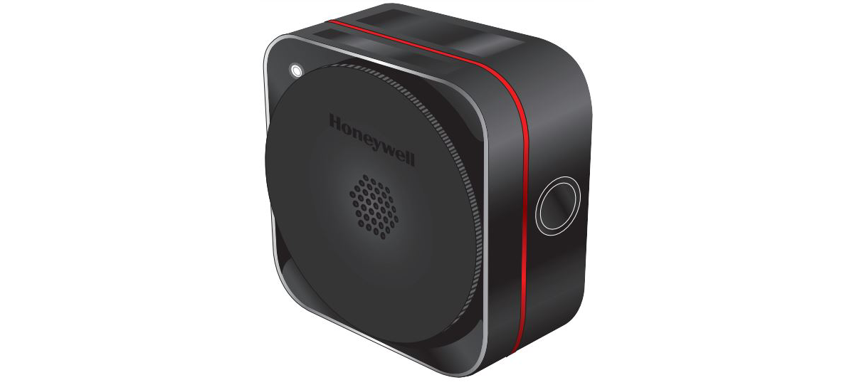
SPLCO1BARCXNZZ
Bluetooth-enabled Sensepoint XCL oxygen detector, 0–25.0% vol default range, charcoal housing and source/sink 4–20 mA output. Includes two changeover relays. For ordinary locations; 11–32 V DC or 20–27 V AC supply.
Warranty coverage and terms are confirmed with your order.
We coordinate the fastest available shipping option for your destination.
Available payment methods are handled through secure payment channels.
Carrier and delivery options are confirmed for your destination before dispatch.
Independent supplier: Xindustra is not an authorized distributor, reseller, or representative of Honeywell. Brand names are used for identification and compatibility purposes only. Read disclaimer
Gas configuration, fitted output hardware and installation details for SPLCO1BARCXNZZ.
SPLCO1BARCXNZZ is a complete Bluetooth-enabled Sensepoint XCL single-sensor fixed gas detector for commercial and light-industrial ordinary locations. It uses electrochemical sensing, a charcoal polycarbonate enclosure and a configurable source/sink 4–20 mA interface. This exact version also includes two changeover relays. It is not the hazardous-area Sensepoint XRL.
SPLCO1BARCXNZZ
Oxygen (O2)
Electrochemical
0–25.0% vol
Charcoal
Ordinary / non-hazardous locations only
4–20 mA, configurable source or sink
Two changeover relays fitted
Not fitted — these are analog BA versions
Bluetooth Low Energy for commissioning and maintenance
| Parameter / condition | Value | Interpretation |
|---|---|---|
| Factory measurement scale | 0–25.0% vol | Oxygen volume concentration |
| Selectable full scale | Fixed 25.0% vol full scale | Fixed full scale |
| Alarm 1 default | 23.5% vol, rising | High-oxygen alarm |
| Alarm 2 default | 19.5% vol, falling | Low-oxygen alarm |
These are detector alarm settings, not a guarantee that both relay contacts are assigned to the two gas alarms. Match the controller scale to the detector’s configured full scale.
Oxygen monitoring on a fixed volume-percent scale, with separate high-oxygen and low-oxygen alarm directions. Alarm 1 is the rising high-oxygen alarm; Alarm 2 is the falling low-oxygen alarm. It is not a combustible-gas %LEL or toxic ppm detector.
Bluetooth is the local commissioning and maintenance interface. It does not add a Modbus terminal interface to an analog detector or make the phone the permanent gas-control output. The complete MPN distinguishes analog/no-relay and analog/relay hardware even though their housings look alike.
24 V DC or 24 V AC, 50/60 Hz
11–32 V DC
Analog-model range, measured at the detector terminals.
20–27 V AC
Certified isolated power supply
Less than 850 mA
1.1 W
Sensor/analog normal-state value plus 0.6 W relay allowance.
1.8 W
Sensor/analog alarm-state value plus 0.6 W relay allowance.
0–22 mA; 4–20 mA measurement interface
33–250 Ω
Pluggable rising-clamp terminals, 0.5–1.5 mm² (20–16 AWG)
+24 V DC / one 24 V AC supply leg
0 V DC / other 24 V AC supply leg
4–20 mA signal
Common
Use the common connection for an external supply/controller grounding arrangement. AC-powered signal loop uses terminals 3 and 4.
Installation manual 3017M5002_4, p.19. Use the detector source configuration and the illustrated load/common arrangement. The opposite side of the figure is the controller, not another detector terminal strip.
Installation manual 3017M5002_4, p.19. Sink and source are alternative arrangements; set the physical selector for the actual connected circuit before applying power.
The mA output needs the documented load even when the installation uses the fitted relays for local signaling. When the current output is unused, the manual specifies a 33 Ω, 0.125 W load between terminals 3 and 2 in source mode, or between terminals 3 and 1 in sink mode. An open output can create a fault.
Two changeover relays, each NC / COM / NO
5 A at 24 V DC or 250 V AC
Manual rating; choose load protection for the actual connected circuit.
Any fault; normally energized
Gas Alarm 1; normally de-energized
Configurable through the mobile app
Installation manual 3017M5002_4, p.10: 1 = normally closed, 2 = common, 3 = normally open. Relay hardware is fitted on this BAR version.
The default relay allocation is one fault relay plus one Alarm 1 relay. Use the app to configure the required assignments; do not wire the unit as if it had the XCD’s three-relay layout.
The physical inhibit selector provides 2 mA for every gas type, or 17.4 mA on the oxygen version. Start-up and maintenance inhibit must be distinguishable from a normal measurement at the receiving controller. Disconnect power before changing source/sink selector position.
113 × 113 × 59 mm
500 g
Polycarbonate, charcoal
IP65; Type 4 in accordance with NEMA 250
Not a hazardous-area or explosion-protection approval.
−20 to +50 °C
0 to +30 °C
15–90% RH, non-condensing
90–110 kPa
4 mm (No.8) diameter; minimum 25 mm length
M20 or ½-inch NPT gland size
M25 or ¾-inch NPT gland size
Installation manual 3017M5002_4, p.10, dimensions in mm and inches. Cable glands, cable bend radius and access space add to the body dimensions.
The XCL is not for a classified hazardous location. Indoors or in a sheltered outdoor position, keep it away from direct UV light and rain. Place the sensing point according to the potential gas release and ventilation, and leave access for sensor service and calibration-gas application.
The back box has four cable-entry knockouts across its sides and rear. Fit suitable glands to the opened entry size; do not treat the inner and outer knockout diameters as four pre-threaded factory ports. Secure the back box and cables without obstructing the detector module.
Fixed 25.0% vol full scale
20.9% vol oxygen
300 mL/min
3 minutes
<30 s
Manual test conditions; not a guarantee over the complete environmental range.
0.1% vol
SPXCLZZO1SS
Sensor-only service part, separate from the complete detector MPN.
The Sensepoint mobile app uses the detector QR code or activation key and device serial number to associate the unit and establish a Bluetooth connection. Local wireless range is up to 10 m and depends on the mobile device and installation. Keep the registration sheet available for commissioning and later service access.
The detector has a multicolor status light, not a local numerical LCD. Green indicates normal operation, red flashing indicates an alarm, yellow flashing a fault, and steady yellow an inhibited state; blue identifies pairing/connection. Normal green behavior is user-configurable. Use the app or connected controller to read the concentration.
The detector is factory pre-calibrated. During commissioning, check the gas response and recalibrate if needed, confirm the full scale at both detector and controller, and test the intended alarm/fault path. Configure the source/sink circuit and inhibit level with power isolated before final energization.
Use the SPXCLCAL calibration/flow cap for calibration. The integrated remote gassing connection can carry bump-test gas to a difficult-to-access unit; it does not replace the calibration cap. Fit a regulator and tubing suitable for the target gas, and route the exhaust away from people.
The manual specifies bump testing at least twice a year. Apply a known reference gas above the relevant threshold, observe the response under the intended test/inhibit procedure, and investigate or calibrate after a failed test. The selected gas uses three minutes of stabilization at 300 mL/min in the calibration-cap table.
Replace the sensor with the matching documented service part and follow the app/manual maintenance sequence. A new cartridge is not a complete detector purchase and does not change the installed wired-interface or relay hardware configuration.
Order the exact product and condition your project requires, with assistance from quotation through delivery.
Your quotation references the complete manufacturer part number to keep the requested product clear.
Tell us whether you need new original, new surplus, used, refurbished or repaired equipment.
Shipping options are prepared around your destination, quantity and requested delivery date.
Access available manufacturer product data, manuals and certificates associated with the order number.