
Exact product identification
Your quotation references the complete manufacturer part number to keep the requested product clear.
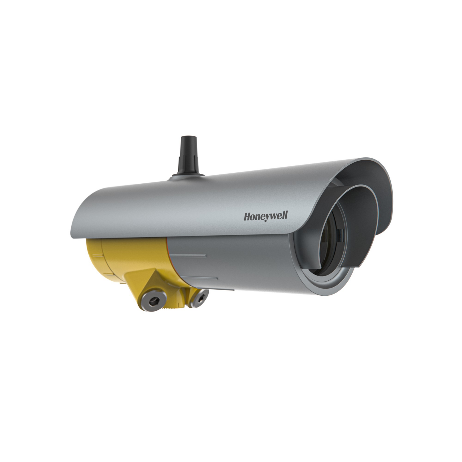
SLXL-PSNGXX
Complete stainless-steel Searchline Excel Plus transmitter/receiver kit, 2 × ¾-inch NPT entries per instrument. 2–120 m optical path, 0–5 LEL·m, receiver 4–20 mA/HART, Modbus and three relays. Includes universal mounts and plastic sunshades.
Warranty coverage and terms are confirmed with your order.
We coordinate the fastest available shipping option for your destination.
Available payment methods are handled through secure payment channels.
Carrier and delivery options are confirmed for your destination before dispatch.
Independent supplier: Xindustra is not an authorized distributor, reseller, or representative of Honeywell. Brand names are used for identification and compatibility purposes only. Read disclaimer
Complete-system contents, path-integrated measurement, power, receiver wiring and optical installation for SLXL-PSNGXX.
SLXL-PSNGXX is the stainless-steel Searchline Excel Plus open-path flammable hydrocarbon gas detection system with ¾-inch NPT cable entries. It includes a transmitter and a receiver, with a universal mounting bracket and plastic sunshade for each end. It covers a 2–120 m optical path and sends the measured gas signal from the receiver. It is not a receiver-only or transmitter-only replacement.
SLXL-PSNGXX
Searchline Excel Plus
One transmitter and one receiver
2 × ¾-inch NPT
Stainless steel
Universal mounting bracket for each instrument
Plastic sunshade for each instrument
Certified blanking plug, tool kit and quick start guide per box
Pole kit, alignment scope, functional test filters and gassing cell ordered separately
2–120 m
0–5 LEL·m
Universal Hydrocarbon
T90 less than 3 seconds
1 LEL·m / 3 LEL·m
0.5 LEL·m
4–20 mA with HART
Modbus RS485, three SPDT relays and Bluetooth
The receiver measures gas integrated along the beam, not the concentration at one point or the leak position. For a uniform cloud, 100% LEL across 1 m and 10% LEL across 10 m both produce 1 LEL·m. The 120 m path rating describes the permitted spacing between the two instruments; it does not change the normal 0–5 LEL·m output scale.
The normal factory calibration is Universal Hydrocarbon. The manual documents hydrocarbon responses including methane, ethane, propane, butane, pentane, hexane, ethylene and propylene. Gas-specific ppm·m scales depend on the selected factory gas calibration; they are not a single universal ppm conversion. These two ordering codes distinguish cable-entry threads, not eight different gas calibrations.
Choose this ¾-inch NPT kit for installations using matching certified NPT glands or conduit fittings. Both transmitter and receiver have two NPT entries. The M25 kit is a separately ordered configuration; do not treat the two threads as interchangeable.
18–32 V DC, nominal 24 V DC
0.7 A / 0.6 A
0.5 A for less than 20 ms
0.3 A for less than 20 ms
17 W
10 W above −30 °C; 15 W below −30 °C
Allow the 15 W heater case for cold-location design.
Approximately 20 minutes
Less than 5 minutes
Less than 1 hour
Galvanic isolation from mains for receiver and current-loop supplies
| Parameter / condition | Transmitter | Receiver |
|---|---|---|
| −55 to −30 °C | 11.8 W | 7.4 W |
| −30 to +30 °C | 5.6 W | 4.8 W |
| Above +30 °C | 3.8 W | 3.0 W |
Average RMS operating values from the manual. Size the supply and cables for cold start and heating, not just these running values; maintain at least 18 V DC at each instrument.
Source or sink, three-wire; isolated, four-wire
Selected by wiring and jumpers, not automatic mode selection.
Less than 600 Ω
Includes cable resistance and receiving input impedance.
250 Ω
100 Ω
32 V DC / 22 mA
5 = mA+; 6 = mA−
7/8 = +24 V; 9/10 = 0 V
7 and 8 are internally linked; 9 and 10 are internally linked.
20 = HART+; 21 = HART−
0.25–2.5 mm² (24–12 AWG)
0.5–0.6 N·m
Greater than 80 °C
2017M1220 Issue 4, p.35, Figure 22. Retain the shown jumper between positive supply and mA+; match the controller load and common connections.
2017M1220 Issue 4, p.35, Figure 23. Sink mode uses a different jumper and current path from source mode.
2017M1220 Issue 4, p.36, Figure 24. Separate V1 detector power and V2 loop power are shown; do not add a source/sink jumper to this isolated arrangement.
For an unused mA output, the manual requires a jumper from terminal 5 to terminal 8 and a load from terminal 6 to terminal 9. The specified load is 470 Ω, ¼ W, or 250–400 Ω when HART is needed. This keeps the analog interface correctly terminated while other outputs are used.
Power the transmitter through terminals 7/8 and 9/10; it does not duplicate the receiver’s mA, Modbus or relay outputs. The manual’s reverse-polarity option disables only the transmitter status LED. It is not a receiver operating mode; keep receiver supply polarity correct.
Important fit check
Isolate both instruments before wiring. Bond the internal protective earth and the external supplementary earth as documented, terminate unused conductors, and use certified glands and blanking plugs for the actual entry thread. The supplied plastic transport cap is not a certified permanent closure.
| Parameter / condition | Analog level | Meaning |
|---|---|---|
| Measurement | 4–20 mA | Proportional to 0–5 LEL·m in proportional mode |
| Fault | 1 mA default | Fault, including persistent beam blockage |
| Inhibit | 2 mA default | Maintenance / inhibited output |
| Warning | 3 mA default | Service or alignment attention |
| Beam-block warning | 2.5 mA if enabled | Intermediate blockage indication; disabled in factory configuration |
| Over-range | 21 mA default | Above configured gas range |
The current output also supports a discrete mode. In that mode normal and alarm conditions use configured fixed current levels rather than a continuous gas-proportional signal.
Three independent SPDT relays
11 COM; 12 NC; 13 NO
14 COM; 15 NC; 16 NO
17 COM; 18 NC; 19 NO
32 V AC/DC, 2 A resistive
Normally energized; configurable
Energization and latching configurable
Fault relay is triggered
The manual identifies the analog output as suitable for SIL 2 applications and the relay outputs as suitable for SIL 1 applications. Select the safety architecture and proof-test procedure for the actual output used; the three relay contacts are not automatically SIL 2 because the detector also has a SIL 2 analog path.
With factory timing, persistent loss of the beam produces a fault after 30 seconds. The intermediate beam-block warning is disabled in factory configuration, so a 2.5 mA warning should not be assumed active. Altering warning/fault delays affects the certified diagnostic interval; retain the default 30-second behavior for the documented functional-safety timing.
HART shares the analog loop; RS485 Modbus uses receiver terminals 1(A), 2(B) and shield terminals 3/4. Bluetooth supports non-intrusive setup and diagnostics with the Honeywell Fixed Platform App, with a stated range up to 20 m under suitable conditions. The LED is a local status indicator, not a numerical concentration display or a safety-related output.
103 mm diameter × 325 mm × 180 mm
Not the complete two-end installation footprint.
6.1 kg / 6.0 kg
3.1 kg per bracket
165 × 165 × 130 mm
The original installation drawing also shows assembled adjustment dimensions.
Within ±45° of horizontal
±0.5°
At least 10 cm
At least 50 cm near the cowling
−55 to +75 °C
0–99% RH, non-condensing
91.5–105.5 kPa, non-compensated
IP66/IP67; Type 4X
2017M1220 Issue 4, p.21, Figure 7. The drawing includes mount and assembled side/front views; allow space for cable bends, aiming and maintenance.
2017M1220 Issue 4, p.17, Figure 4. Keep both the beam corridor and temporary scope access clear.
Aim the transmitter and receiver coaxially across the selected 2–120 m path. Avoid angular vibration, settling supports, steam plumes, vegetation growth and vehicle or pedestrian obstructions. A rigid support is part of the optical installation; a large mounting adjustment range does not permit continuous support movement.
Window heating reduces condensation and frost. It can melt deposited snow or ice down to approximately −20 °C; colder exposed installations may need additional shielding against accumulation. Flooding or deluge can interrupt the optical signal despite the enclosure rating. Keep the windows accessible for inspection and cleaning.
The manual gives gas hazardous-location ratings up to +75 °C, but dust/Class II ratings up to +55 °C. Use the applicable marked certification rather than treating the full operating-temperature envelope as the limit for every hazardous-location classification.
Use the separately ordered 2017B0299 alignment scope for basic and fine alignment. Complete tightening without moving the optical axis, enter the actual path length, confirm alignment quality, and test the receiving loop and alarm/fault paths. Keep the registration/activation details available for the Fixed Platform App.
2017B0299
2017B0218
2017B0185
2331B1102
2331B1020
2017B0113
Apply the appropriate low/high filter at the receiver and compare the response with the receiver’s factory test sheet. The filters are response-test tools, not additional transmitter/receiver system variants. Restore normal state and release inhibit after the test.
The gassing cell checks calibration with a known gas and optical path. Its 138.8 mm gas path determines the LEL·m reading together with gas concentration and that gas’s LEL. Use the calibration-matching gas; a different gas’s cross-sensitivity is not a precise calibration reference. The Fixed Platform App supports this test procedure.
Schedule inspection and functional testing around the site risk and maintenance plan. Inhibit the output while disturbing the optical path, clean with soapy water and a damp soft cloth, and avoid solvents or abrasives. Restore the channel and re-zero using the documented procedure. After deluge, also inspect alignment and run diagnostics before returning the system to normal service.
Order the exact product and condition your project requires, with assistance from quotation through delivery.
Your quotation references the complete manufacturer part number to keep the requested product clear.
Tell us whether you need new original, new surplus, used, refurbished or repaired equipment.
Shipping options are prepared around your destination, quantity and requested delivery date.
Access available manufacturer product data, manuals and certificates associated with the order number.