
Exact product identification
Your quotation references the complete manufacturer part number to keep the requested product clear.
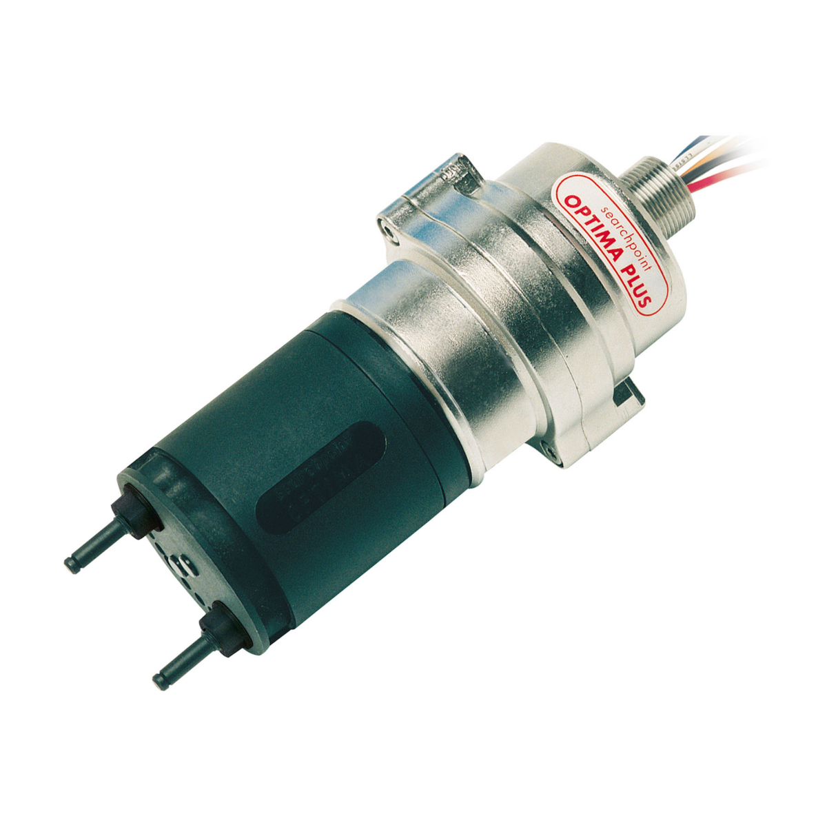
2108N4100N
Searchpoint Optima Plus hydrocarbon-version diffusion detector, UL / Inmetro, ¾-inch NPT, 4–20 mA, non-HART. No factory RGC. 316SS body with dust barrier, weather housing and shade. Target gas and scale are selected by compatible calibration.
Warranty coverage and terms are confirmed with your order.
We coordinate the fastest available shipping option for your destination.
Available payment methods are handled through secure payment channels.
Carrier and delivery options are confirmed for your destination before dispatch.
Independent supplier: Xindustra is not an authorized distributor, reseller, or representative of Honeywell. Brand names are used for identification and compatibility purposes only. Read disclaimer
Detector configuration, gas-calibration selection, electrical integration and installation for 2108N4100N.
2108N4100N is a complete Searchpoint Optima Plus diffusion detector with UL / Inmetro certification, a ¾-inch NPT mounting spigot and 4–20 mA, non-HART output. This package has no factory-fitted remote gassing cell. The stainless-steel detector measures gas at its optical cell; it is not an open-path transmitter/receiver pair.
2108N4100N
Hydrocarbon calibration family
Diffusion, with weather protection and dust barrier
UL / Inmetro
¾-inch NPT
4–20 mA, non-HART
Not fitted
Electropolished 316 stainless steel
Polyester mesh dust barrier, nylon weather housing and deluge/sunshade
Not fitted
Not fitted
The hydrocarbon version identifies an optical/calibration family, not a unique target-gas setting. Choose a compatible hydrocarbon calibration for the intended gas, such as a supported methane or propane calibration. Honeywell specifies a compatible calibration with every complete detector order. The configured target gas, full scale and LEL convention on the unit label must match the receiving controller.
The 4–20 mA measurement represents 0–100% of the selected full scale. %LEL calibrations are gas-specific; %LEL is not the same as percent gas by volume. The special high-concentration methane/propane sampling packages are different order codes, not a feature added to these diffusion versions by fitting an RGC.
Choose the hydrocarbon version for a supported hydrocarbon gas calibration. The non-HART version keeps the standard analog measurement interface and uses the documented SHC1/XNX service arrangement for configuration. The ¾-inch NPT, UL/Inmetro configuration is a different ordered approval/thread package from the M25 ATEX/IECEx units. Use the standard weather-protected gas inlet for local response checks.
24 V DC
18–32 V DC
5 W
Three-wire, automatic current source or sink
600 Ω
In current-source mode at 18–20 V DC, maximum 500 Ω.
Positive DC supply
0 V DC
4–20 mA measurement signal
RS485 A / B for proprietary SHC1 communication
Not a general-purpose Modbus RTU interface.
Protective earth
Honeywell MAN0905 Issue 7, p.28. Source-mode load is between the controller signal and common. Preserve the illustrated shield/earth arrangement and the stated load limit.
Honeywell MAN0905 Issue 7, p.29. Source and sink are alternative controller circuits; the detector selects the operating mode automatically.
Size the supply cable so the detector still receives at least 18 V DC at its maximum power demand. Supply cable loop resistance and the receiving controller’s analog load are separate calculations; a 600 Ω signal-load allowance is not permission to put 600 Ω in the power cable.
The analog measurement is available to a suitable gas controller. Configuration and detailed diagnosis use the manufacturer’s SHC1 handheld/proprietary RS485 connection or the documented XNX interface. Connecting a HART handheld to the analog loop does not add HART capability to this N-suffix unit.
| Parameter / condition | Default current | Controller interpretation |
|---|---|---|
| Fault | Less than 1 mA | Detector fault, not a valid zero-gas reading |
| Inhibit | 2 mA | Maintenance or inhibited measurement |
| Warning | 3 mA | Service warning; gas monitoring continues and a detected gas reading takes priority |
| Measurement | 4–20 mA | 0–100% of the configured gas full scale |
| Over-range | 21 mA | Gas above the configured scale |
Factory defaults; several status currents are configurable. Program the receiving controller for the installed settings rather than treating every below-4 mA signal as the same state.
The detector head has no integral numeric display or relay contacts. A suitable receiving controller supplies the concentration indication and site alarm actions. An XNX transmitter, OELD display, junction box or other interface is separate equipment, not included merely because it is shown elsewhere in the Optima Plus ecosystem.
Less than 4 seconds
Less than 3 seconds
T90 18 seconds; T50 6 seconds
Manufacturer methane reference conditions. Other gases/calibrations may respond more slowly.
The very fast bare-optics figure excludes the weather housing and dust barrier supplied with this package. Use the protected-detector response reference for that arrangement, then account for the chosen gas and installation rather than advertising the bare-head figure as the installed response.
The optical self-check and warning channel support maintenance before contamination becomes a full fault. A warning is not a substitute for a gas response check, and it must be distinguished from inhibit and fault at the receiving controller.
165 mm long × 73 mm diameter
Detector body dimensions, not the complete junction-box, shade and tubing installation envelope.
1.6 kg
Horizontal
¾-inch NPT
IP66 / IP67
−40 to +65 °C
Less than 3 °C per minute
0–99% RH, non-condensing
80–120 kPa
Uncompensated pressure range.
Mount the detector horizontally in a suitable certified enclosure or mounting arrangement with its ¾-inch NPT spigot. Fit the standard weather protection with its semicircular openings facing downward. Use the certified NPT connection arrangement appropriate to this approval variant; the M25 washer-and-locknut detail is not the NPT thread specification. Keep access for cleaning and gas checks.
The deluge/sunshade fits over the standard weather protection with its longer overhang toward the front. Keep its clamp clear of the gas vent slot. Allow space for the junction box, outgoing cables and any test tubing in addition to the bare detector dimensions.
Keep steam, hot condensate and direct contamination away from the optical path. The detector is rated for a wide ambient range, but a temperature change faster than 3 °C/min is a separate limit and can cause faults or damage. Place the sensing point according to gas-release and ventilation behavior, not simply where the cable is easiest to route.
The detector is factory calibrated. Allow one hour powered stabilization before gas testing or calibration work. Establish the site test/inhibit procedure, confirm the detector/controller scale agreement and verify the intended warning, fault and alarm paths before returning the channel to service.
Gassing cover 2108D0258
1–1.5 L/min
30–60 seconds
Calibration cap 2108B0272
Different accessory from the bump-test gassing cover.
Apply the selected reference gas through the documented gassing cover for a functional response check. A calibration operation uses the separate calibration cap and the manual’s preparation sequence. This package does not have a factory RGC; local gassing cover flow is not the 0.3 L/min RGC flow.
Honeywell states that Optima Plus does not require routine calibration. Schedule inspections and gas response checks for the actual installation conditions, and investigate failed checks or contamination warnings. Where adjustment is needed, follow the gas-specific zero/span procedure rather than imposing a generic six-month recalibration rule from another detector family.
Remove contamination with the documented mild detergent and a soft cloth or cotton bud. Do not use solvents or abrasives. Restore the dust barrier, weather protection and shade in their correct positions after service, then complete the required response check before removing inhibit.
Order the exact product and condition your project requires, with assistance from quotation through delivery.
Your quotation references the complete manufacturer part number to keep the requested product clear.
Tell us whether you need new original, new surplus, used, refurbished or repaired equipment.
Shipping options are prepared around your destination, quantity and requested delivery date.
Access available manufacturer product data, manuals and certificates associated with the order number.