
Exact product identification
Your quotation references the complete manufacturer part number to keep the requested product clear.
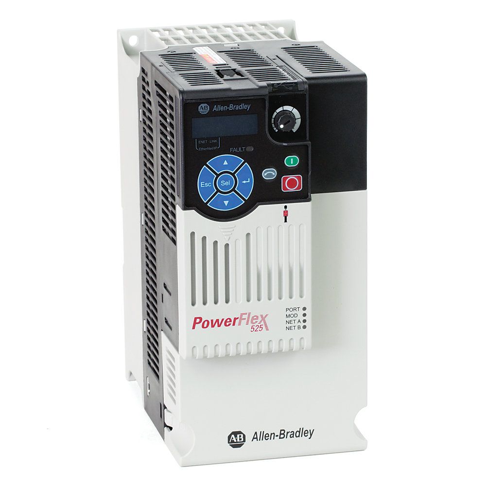
25B-D013N114
380–480 V three-phase PowerFlex 525 drive with 13 A output, 5.5 kW normal-duty and heavy-duty motor rating, Frame C, integrated EMC filter, EtherNet/IP and Safe Torque Off.
Warranty coverage and terms are confirmed with your order.
We coordinate the fastest available shipping option for your destination.
Available payment methods are handled through secure payment channels.
Carrier and delivery options are confirmed for your destination before dispatch.
Independent supplier: Xindustra is not an authorized distributor, reseller, or representative of Allen-Bradley. Brand names are used for identification and compatibility purposes only. Read disclaimer
Motor-duty ratings, Frame C installation, power/control connections and built-in safety for 25B-D013N114.
25B-D013N114 is a filtered, IP20/open-type PowerFlex 525 AC drive for a 380–480 V three-phase supply. The Frame C power module combines the common PowerFlex 525 control platform with a larger current rating and a 109 mm-wide cabinet footprint.
| Parameter / condition | Normal Duty | Heavy Duty |
|---|---|---|
| Motor power | 5.5 kW | 5.5 kW |
| Motor power in horsepower | 7.5 HP | 7.5 HP |
Normal Duty and Heavy Duty both list 5.5 kW / 7.5 HP for this model. Size the motor by its nameplate current as well as horsepower, and retain the current derating required by the cabinet temperature, altitude and carrier frequency.
25B-D013N114
Allen-Bradley
PowerFlex 525; Bulletin 25B
380–480 V AC; three-phase
323–528 V AC
47–63 Hz
13 A
Three-phase
0–500 Hz
Programmable; motor and application limits remain part of the configuration
C
IP20 / NEMA open type
Integrated
Included
2–16 kHz
Drive current rating is based on 4 kHz
The N114 suffix selects the IP20/open-type drive with the standard interface, integrated EMC filter and standard braking configuration. N104 is the unfiltered order number, not an interchangeable suffix for the same EMC installation.
Three-phase AC line input
Motor output
DC bus connection
Dynamic braking resistor connection
Shared positive terminal in the original terminal drawing
Protective earth
Frame C power terminals
520-UM001O-EN-E, page 36. Original terminal layout with line, motor, DC bus, braking and protective-earth labels.
2.1–8.4 mm²
Mechanical terminal capacity; not a conductor-sizing recommendation
1.76–2.16 N·m
0.13–1.3 mm²
0.71–0.86 N·m
Input fuses or a suitable circuit breaker provide branch short-circuit protection; this is not supplied by the drive. The technical data has separate UL and IEC selection tables. Use the drive’s control inputs for normal starts and stops rather than repeatedly switching the AC line supply.
The internal brake IGBT can switch a separately selected resistor for a braking duty that returns energy to the DC bus. The resistor’s resistance, power and duty cycle are separate selections. An included brake IGBT does not mean that a brake resistor or mechanical motor brake is included.
On an ungrounded or resistive-grounded supply, the manual requires the ground-referenced MOV connection to be disconnected as applicable to that supply arrangement. On a drive with an embedded filter, this also disconnects the filter capacitor from earth. The resulting EMC arrangement differs from operation with the filter connected to earth.
One embedded port for drive configuration and control
Integral RS-485 / DSI
Integral keypad, potentiometer and display
One dedicated stop input plus six programmable inputs
Two isolated channels: voltage and current
0–10 V or ±10 V; terminal 13
4–20 mA; terminal 15
Terminal 07; NPN pulse input up to 100 kHz
Two programmable contacts: one normally open, one normally closed
Two; 30 V DC, 50 mA, noninductive
One nonisolated voltage/current output
PowerFlex 525 control-terminal map
520-UM001O-EN-E, page 42. Includes SRC/SNK input selection, analog connections, output contacts and STO terminals. The two-wire circuit is shown; use the programmed start/stop mode for three-wire control.
J5 selects SRC/SNK digital input wiring; J9 selects terminal 07 as a digital or pulse input; J10 selects the analog output voltage/current circuit. Terminal 01 remains a stop input under every start-source mode. The factory jumper between 01 and 11 is removed when 01 is used as a wired stop or enable input. Fit a recovery diode across an inductive load driven by an opto output, as shown in the original diagram.
Connected Components Workbench supports drive setup. MainsFree USB configuration transfers settings through the detachable control module without powering the drive’s main AC input. Studio 5000 Logix Designer supports the controller integration workflow over EtherNet/IP with the appropriate drive profile. Select the command and speed-reference sources in the drive configuration rather than relying on the presence of an Ethernet cable alone.
The embedded EtherNet/IP port is standard. A dual-port/DLR network topology uses the separate dual-port EtherNet/IP option card. DeviceNet, PROFIBUS and encoder interfaces are optional selections, not supplied interfaces inferred from the base drive’s network capability.
C
109 mm
220 mm
184 mm
2.3 kg
DIN rail or screws
M5
1.56–1.96 N·m
175 W
For the selected filtered catalog entry; use when estimating cabinet heat load
| Parameter / condition | Maximum without current derating | Maximum with current derating | Maximum with optional control-module fan kit |
|---|---|---|---|
| Vertical, separate drives | 50 °C | 60 °C | 70 °C; derated |
| Vertical, zero side clearance | 45 °C | 55 °C | 65 °C; derated |
Minimum operating temperature: −20 °C. The fan kit is separately ordered. These limits do not mean full output current is available at the highest temperature.
Vertical-mount current derating
520-TD001I-EN-E, page 17. Use the IP20/Open Type curve for this base drive. Dashed curves require the optional control-module fan kit; IP30/NEMA1 curves refer to a different enclosure configuration.
For ordinary vertical mounting, provide 50 mm above and below the drive and 25 mm between adjacent drives. Zero-side-clearance mounting has the lower temperature limits shown in the matrix. Horizontal mounting requires the optional control-module fan kit and is not the standard no-kit installation.
Up to 1000 m
Derating required; 480 V center-grounded wye supply up to 4000 m, other listed grounding arrangements up to 2000 m
−40 to +85 °C
0–95%; noncondensing
Pollution degree 1 or 2; enclosure and cooling protection required
The technical data permits either a 10% output-current reduction or a 5 °C ambient-temperature reduction for each additional 1000 m, subject to the supply-grounding altitude ceiling. Higher-altitude use is therefore not the sea-level rating with the same full load and temperature.
PowerFlex 525 includes two-channel Safe Torque Off through S1, S2 and S+. The function blocks torque-producing switching in the drive’s output stage. The drive’s STO function supports Category 3 / PLd and SIL 2 when applied as part of the corresponding validated safety control system; it is not a separate safety PLC.
Safety input 1
Safety input 2
Safety +24 V; internally tied to the drive’s terminal 11 supply
100 ms
Maximum input-condition-to-STO initiation time
Both channels form the hardwired STO circuit
Important fit check
STO removes the drive’s ability to produce motor torque; it does not isolate the AC input, DC bus or motor conductors. Hazardous voltage can remain present. Electrical maintenance requires supply isolation and verification that the DC bus and motor voltage have discharged.
Enter the motor nameplate voltage, current and frequency, select the correct motor-control mode, and set start/stop and speed-reference sources. The dedicated stop circuit, external STO circuit and network command path perform different jobs. Safety-system design and validation remain part of the machine integration, not a feature supplied automatically by connecting S1/S2.
Official specifications, installation guidance and exact-model resources.
Order the exact product and condition your project requires, with assistance from quotation through delivery.
Your quotation references the complete manufacturer part number to keep the requested product clear.
Tell us whether you need new original, new surplus, used, refurbished or repaired equipment.
Shipping options are prepared around your destination, quantity and requested delivery date.
Access available manufacturer product data, manuals and certificates associated with the order number.