
Stored-energy safety tool
Capacitor safety discharge calculator
Estimate how long a capacitor takes to fall from an initial voltage to a non-zero target, calculate the bleeder resistance required for a target time, or find the remaining voltage after a known interval. The results also show stored energy, initial current and initial resistor power.
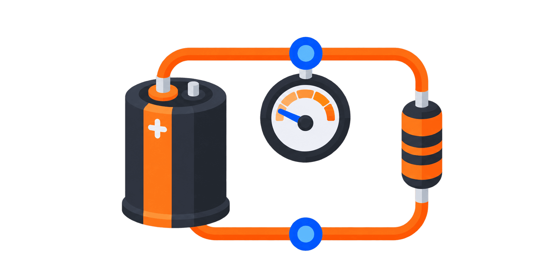
Discharge time result
Discharge resistance
100 kΩ
Time to target
1.6289 min
Remaining voltage
50 V
12.5% of initial voltage
RC time constant
47 s
τ = R × C
Initial current
4 mA
I₀ = V₀ ÷ R
Initial resistor power
1.6 W
P₀ = V₀² ÷ R
Initial stored energy
37.6 J
E₀ = ½CV₀²
Energy dissipated
37.0125 J
Remaining 587.5 mJ
Confirm the real circuit before contact
Use a rated measuring instrument and the equipment manufacturer’s procedure. Verify resistor working voltage, pulse energy, continuous power, tolerance and failure mode; do not treat elapsed time alone as proof that the capacitor is safe.
Voltage decay
Ideal exponential discharge through a fixed resistance.
V(t) = V₀e−t/RC
How to use the capacitor discharge calculator
Use the mode that matches the unknown quantity, then evaluate the electrical and safety limits of the real discharge path.
- 01
Choose the quantity to solve
Calculate discharge time, solve for bleeder resistance, or calculate the voltage remaining after a known elapsed time.
- 02
Enter capacitance and initial voltage
Use the effective capacitance at the actual voltage and temperature when that information is available, not only the nominal marking.
- 03
Define the resistor, target voltage or time
Enter the fixed discharge resistance for time or remaining-voltage calculations, or enter a required time when sizing the resistor.
- 04
Review energy and resistor stress
Check initial power, stored energy, working voltage and the decay curve, then verify the result with the equipment procedure and a suitably rated instrument.
Ideal capacitor discharge relationships
The calculator models one capacitor discharging through one fixed resistor with no external source connected.
Voltage after time
V(t) = V0 × e^(−t/RC)
Time to target voltage
t = R × C × ln(V0 / Vt)
Required resistance
R = t / [C × ln(V0 / Vt)]
RC time constant
τ = R × C
Stored capacitor energy
E = ½ × C × V²
Initial resistor power
P0 = V0² / R
An ideal RC discharge approaches zero voltage asymptotically, so a target of exactly zero cannot produce a finite calculated time. Real capacitance, leakage, resistor tolerance, temperature and dielectric absorption can change the measured curve. Initial resistor power is the highest instantaneous value for a passive discharge, while the total pulse energy is associated with the capacitor’s stored energy.
This calculator is not a declaration that equipment is safe to touch. Isolate all energy sources, follow lockout and manufacturer procedures, use a correctly rated measuring instrument, and verify the voltage directly. Select the discharge resistor using its working-voltage, pulse-energy, overload, continuous-power, creepage, temperature and failure-mode ratings; do not select it from resistance and nominal wattage alone.
Checks before relying on a discharge result
The ideal exponential curve is useful for design estimates, but safe work requires a verified discharge path and direct measurement.
Use worst-case capacitance and resistance
Include component tolerance, voltage dependence, temperature and aging where they can lengthen the discharge time.
Check pulse energy and working voltage
Confirm the resistor or resistor network can withstand the initial voltage, short-duration power and full discharge energy using manufacturer pulse data.
Check continuous dissipation
A permanently connected bleeder dissipates V²/R while the bus is energized. Apply the required temperature derating and enclosure thermal limits.
Allow for dielectric absorption
Some capacitors can recover a measurable voltage after an apparent discharge. Recheck the terminals and follow the manufacturer’s handling procedure.
Verify the discharge path cannot be interrupted
Switches, fuses, connectors, relays or failed resistors can open the intended path. Use the topology and monitoring required by the equipment design.
Measure before contact
Elapsed time and an indicator are not substitutes for a suitably rated meter and the prescribed prove-test-prove procedure.
Capacitor discharge calculator questions
Why can’t the target voltage be zero?
The ideal exponential equation approaches zero but never reaches it in a finite time. Enter a positive target defined by the equipment procedure or applicable requirement.
Is the calculated initial power the resistor wattage I need?
No. It is the instantaneous starting power. Selection must also consider discharge energy, pulse duration, repetition, working voltage, ambient temperature and continuous power while the circuit is energized.
Where does the capacitor’s stored energy go?
For a simple passive discharge, the resistor converts the reduction in stored electrical energy into heat. Other circuit elements and parasitics can share some of that energy in a real system.
What is a bleeder resistor?
A bleeder resistor is connected across a capacitor or DC bus so stored charge decays after the source is removed. Its connection and ratings must remain valid under the equipment’s expected fault conditions.
Why did the voltage rise again after discharge?
Dielectric absorption can cause charge redistribution and voltage recovery after the initial discharge path is removed. Leakage, switching paths and external sources can also produce unexpected voltage.
Related engineering tools
Time constant calculator
Compare the same first-order RC relationship across standard response intervals.
Open resource
Reactance calculator
Calculate ideal capacitor or inductor reactance at a selected frequency.
Open resource
Power factor calculator
Estimate AC power relationships and ideal capacitive correction requirements.
Open resourceAll engineering tools
Browse Xindustra’s tested electrical, timing, component and RF calculators.
Open resource