
Exact product identification
Your quotation references the complete manufacturer part number to keep the requested product clear.
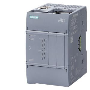
6ES7214-1AH50-0XB0
SIMATIC S7-1200 G2 CPU 1214C DC/DC/DC: 20.4–28.8 V DC, nominal 24 V DC, 14 digital inputs, 10 transistor outputs, 250 KB program and 750 KB data memory. Two-port PROFINET, 10 external modules and 2 expansion boards.
Warranty coverage and terms are confirmed with your order.
We coordinate the fastest available shipping option for your destination.
Available payment methods are handled through secure payment channels.
Carrier and delivery options are confirmed for your destination before dispatch.
Independent supplier: Xindustra is not an authorized distributor, reseller, or representative of Siemens. Brand names are used for identification and compatibility purposes only. Read disclaimer
Supply, onboard I/O, G2 expansion, engineering and installation data for 6ES7214-1AH50-0XB0.
6ES7214-1AH50-0XB0 is a SIMATIC S7-1200 G2 standard compact CPU with 14 onboard 24 V DC digital inputs and 10 24 V DC transistor outputs. It operates from a 24 V DC control supply. The 1214C provides more local I/O, memory and expansion capacity than the 1212C.
6ES7214-1AH50-0XB0
SIMATIC S7-1200 G2
CPU 1214C DC/DC/DC
Standard compact PLC
14 × 24 V DC, sourcing/sinking
10 × 24 V DC transistor
0 / 0
250 KB
750 KB
1000 KB
20 KB
A retentive area, not additional work memory.
8 MB
Up to 32 GB
10 total SM + CM/CP
Communications modules occupy positions within this total.
Up to 10, depending on CM configuration
Up to 3, within the total module limit
2 SB/CB/BB
1600 mA maximum
400 mA maximum
A configuration that fits the 10-module count can still exceed the 1600 mA backplane or 400 mA sensor-supply budget. Use G2-compatible signal modules and boards for additional analog or digital channels; this CPU has no onboard analog input or analog output.
20.4–28.8 V DC, nominal 24 V DC
145 mA
1,000 mA
12 A at 28.8 V DC
3.5 W
At least L+ minus 4 V
400 mA maximum
24 V DC
5 V DC or 0.5 mA
15 V DC at 2.5 mA
Sourcing or sinking
6 at up to 100 kHz single-phase; 2 at up to 30 kHz
6 at up to 80 kHz; 2 at up to 20 kHz
500 m shielded / 300 m unshielded
50 m maximum, shielded
10
0.5 A maximum per output
5 W maximum
4 × 100 kHz, Qa.0–Qa.3
Up to 20 kHz
1 μs / 3 μs maximum
500 m shielded / 150 m unshielded
The DC/DC/DC version uses powered transistor outputs for 24 V DC loads and pulse control. Qa.0–Qa.3 provide the four 100 kHz channels. Allocate channels for the selected pulse/direction or pulse-up/pulse-down mode rather than treating four fast channels as four complete axes.
DC/DC/DC means a DC-powered CPU, 24 V DC digital inputs and 24 V DC transistor outputs. It is a different output circuit from the RLY variants even where the CPU size and input count match.
Siemens A5E52923928-AA, V1.0 01/2025, p.274. Original physical terminal wiring for this CPU configuration; retain the shown connector keying and commons.
1
2, integrated switch
100 Mbit/s
IO Controller and IO Device
Supported
31 maximum
Not supported
Server with Basic runtime license
Supported
Supported with suitable serial CB/CM
Integrated web server and Web API
The two RJ45 sockets provide an integrated switch for the same interface. They are not two independent routed networks. Serial Modbus requires a suitable communications board or module; there is no integral RS485 terminal just because Modbus RTU appears in the supported-protocol list.
V4.1
STEP 7 V21 or higher
LAD, FBD, SCL
800
40
40 / 80 / 160
No — standard CPU
Technology objects consume the shared Motion Control budget; the resource total is not a guarantee of the same number of physical pulse axes. Select the drive interface, cycle time and output hardware together. Standard G2 CPUs and FC fail-safe CPUs are separate products.
The current V4.1 data sheet lists an OPC UA server for read, write, subscription and method calls. A Basic runtime license is required; it is not included merely by selecting this CPU order number.
80 × 125 × 100 mm
352 g
IP20
−20 °C, non-condensing
Up to 40 °C, all mounting positions
60 °C
Rated voltages, 50% of maximum specification and alternate I/O active.
50 °C
Rated voltages, 50% of maximum specification and alternate I/O active.
−40 to +70 °C
Up to 95%, non-condensing
480 hours, maintenance-free and battery-free
The 60 °C horizontal and 50 °C vertical limits do not describe operation with every I/O point at maximum load. Full specified loading is listed up to 40 °C. Include CPU heat loss, expansion-module dissipation and cabinet ventilation in the enclosure design.
A similar 1212C or 1214C name does not make this CPU a drop-in Classic replacement. G2 has different module and board hardware, terminal arrangements and dimensions. Rebuild the bill of materials around compatible G2 modules, allow for the absence of onboard analog I/O, and migrate the engineering project to the supported G2 device and firmware configuration.
| Parameter / condition | CPU 1212C | CPU 1214C |
|---|---|---|
| Onboard digital inputs / outputs | 8 / 6 | 14 / 10 |
| Program / data work memory | 150 / 500 KB | 250 / 750 KB |
| External module positions | 6 total | 10 total |
| Expansion boards | 1 | 2 |
| Body width | 70 mm | 80 mm |
Both sizes offer DC/DC/DC, AC/DC/RLY and DC/DC/RLY variants. Choose the supply and output circuit before comparing capacity.
Order the exact product and condition your project requires, with assistance from quotation through delivery.
Your quotation references the complete manufacturer part number to keep the requested product clear.
Tell us whether you need new original, new surplus, used, refurbished or repaired equipment.
Shipping options are prepared around your destination, quantity and requested delivery date.
Access available manufacturer product data, manuals and certificates associated with the order number.