
Exact product identification
Your quotation references the complete manufacturer part number to keep the requested product clear.
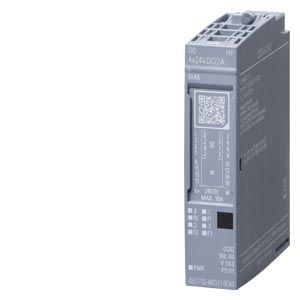
6ES7132-6BD21-0CA0
Four-channel High Feature 24 V DC PNP output module, 2 A per channel, with channel diagnostics, red fault LEDs, MSO and isochronous support. Total current is temperature-dependent.
Warranty coverage and terms are confirmed with your order.
We coordinate the fastest available shipping option for your destination.
Available payment methods are handled through secure payment channels.
Carrier and delivery options are confirmed for your destination before dispatch.
Independent supplier: Xindustra is not an authorized distributor, reseller, or representative of Siemens. Brand names are used for identification and compatibility purposes only. Read disclaimer
Output ratings, load limits and configuration for the DQ 4x24VDC/2A HF.
A four-channel, 2 A PNP output module with channel-by-channel wire-break and short-circuit diagnostics and red channel fault LEDs. High Feature operation adds MSO and isochronous support; it does not add PWM or oversampling.
4
PNP, current-sourcing
24 V DC
2 A
8 A
Subject to mounting orientation and ambient-temperature derating
10 W
12 Ω to 3.4 kΩ
0.1 mA
Electronic
2.8–5.2 A
50 / 100 µs, typical, resistive load
The 2 A channel rating is the usable load-current limit. The electronic short-circuit response threshold is a protection characteristic, not permission to operate a channel above its rated current. Fault diagnostics provide an additional troubleshooting function; they do not increase the channel rating.
| Parameter / condition | Horizontal installation | Vertical installation |
|---|---|---|
| Up to +30 °C | 8 A | 8 A |
| Up to +40 °C | 8 A | 6 A |
| Up to +50 °C | 6 A | 4 A |
| Up to +60 °C | 4 A | Not within rated vertical operating range |
These are maximum module-total currents at the listed ambient-temperature limits, not a higher per-channel rating.
100 Hz
0.1 Hz
Higher rates depend on load current and the permitted switching-frequency curve in the module manual
10 Hz
Typically L+ − 50 V
Not permitted
Supported
Disable “Short circuit to L+” and “Wire break” diagnostics for the paired outputs to avoid false diagnostic messages
The HF diagnostic features do not increase the load rating: use the same 2 A channel limit and temperature-dependent 8/6/4 A module-total limits. For an inductive actuator, use the load-current-dependent switching curve rather than the resistive-load frequency.
24 V DC
Permissible range: 19.2–28.8 V DC
Yes
20 mA
Without load current
1 W
No
Yes
1000 m
600 m
| Parameter / condition | BaseUnit arrangement |
|---|---|
| 1-wire | BU type A0 |
| 2-wire | BU type A0 |
| 3-wire | BU type A0 with AUX terminals, or a potential distributor module |
A light-colored BaseUnit starts a new potential group; a dark-colored BaseUnit continues the voltage buses from the module on its left. Select the module’s potential-group parameter to match the physical BaseUnit arrangement. The electronic module and BaseUnit are separate order items.
DQ0 is available at terminals 1/5, DQ1 at 2/6, DQ2 at 3/7 and DQ3 at 4/8. The second terminal for a channel is another connection to the same output, not an extra channel. The circuit drawing also shows F0–F3 fault indicators.
Schematic circuit diagram
08/2024 · A5E53132307-AB, Figure 4-1. Original output circuit, terminal mapping, supply and backplane-bus connections.
Supported
Channel-by-channel
Channel-by-channel
Yes, red
Supported
Not supported
Supported
Supported
Supported
Maximum 4 bytes; 2 channels per submodule plus QI information
| Parameter / condition | Supported version / integration |
|---|---|
| STEP 7 TIA Portal | V19 with HSP0426; integrated from V20 |
| STEP 7 Classic | V5.5 SP3 with HSP0230 V11.0; integrated from V5.7 SP3 |
| PROFINET | GSDML V2.43 |
| PROFIBUS | GSD revision 5 |
TIA Portal V19 uses HSP0426, while V20 integrates this module. It supports two configurable submodules, a minimum isochronous bus cycle of 500 µs, minimum execution/activation time TCO of 75 µs and maximum jitter of 8 µs. Its diagnostics identify individual channels; do not configure it as the Standard variant.
15 × 73 × 58 mm
Electronic module; excludes BaseUnit and packaging
30 g
−30 to +60 °C
Full stated range for this current module generation
−30 to +50 °C
Full stated range for this current module generation
5000 m
Above 2000 m, additional installation restrictions apply as described in the ET 200SP system manual
CC02
Type A
1 module
6ES7132-6BD21-0CA0 identifies the DQ 4x24VDC/2A HF electronic module in a one-piece packing unit. Order the type A0 BaseUnit separately for the intended wiring arrangement. This is the High Feature 6BD21 generation, not the Standard 0BA0 variant or older 6BD20 model. It is not a fail-safe output module.
Manufacturer data and installation resources for this exact module.
Order the exact product and condition your project requires, with assistance from quotation through delivery.
Your quotation references the complete manufacturer part number to keep the requested product clear.
Tell us whether you need new original, new surplus, used, refurbished or repaired equipment.
Shipping options are prepared around your destination, quantity and requested delivery date.
Access available manufacturer product data, manuals and certificates associated with the order number.