
Exact product identification
Your quotation references the complete manufacturer part number to keep the requested product clear.
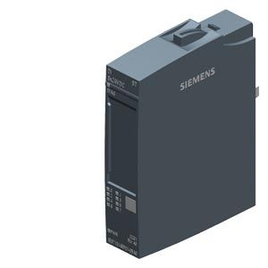
6ES7131-6BF01-0BA0
Eight-channel 24 V DC digital input module for SIMATIC ET 200SP. Accepts PNP signals, offers configurable input filtering and module diagnostics, and fits type A0 BaseUnits.
Warranty coverage and terms are confirmed with your order.
We coordinate the fastest available shipping option for your destination.
Available payment methods are handled through secure payment channels.
Carrier and delivery options are confirmed for your destination before dispatch.
Independent supplier: Xindustra is not an authorized distributor, reseller, or representative of Siemens. Brand names are used for identification and compatibility purposes only. Read disclaimer
Input characteristics, BaseUnit requirements and configuration details for the DI 8x24VDC ST.
Use this module to acquire 24 V DC signals from switches and PNP sensors in an ET 200SP station. It provides standard digital inputs, not counter, oversampling or fail-safe functions.
8
Sinking input for PNP signals (P-reading)
IEC 61131, type 3
24 V DC
−30 to +5 V
+11 to +30 V
2.5 mA
Typical
0.05 / 0.1 / 0.4 / 0.8 / 1.6 / 3.2 / 12.8 / 20 ms
Additional line-length-dependent delay: 30–500 µs
1.5 mA
Maximum permissible
1000 m
Maximum
600 m
Maximum
Short input delays suit fast-changing signals; longer delays suppress short disturbances. The factory parameter setting is 3.2 ms. A signal change is detected only after it persists for the configured delay.
| Parameter / condition | Connection | BaseUnit arrangement |
|---|---|---|
| 1-wire | 1-wire | BU type A0 |
| 2-wire | 2-wire | BU type A0 |
| 3-wire | 3-wire | BU type A0 with AUX terminals, or a potential distributor module |
| 4-wire | 4-wire | BU type A0 plus a potential distributor module |
A light-colored BaseUnit starts a new potential group and supplies its voltage buses. Dark-colored BaseUnits continue the potential group from the module on the left. Set the module’s potential-group parameter to match the BaseUnit arrangement.
BU type A0 with AUX terminals
Siemens module manual, Figure 3-2: terminal assignment and internal circuit for a three-wire sensor connection. The drawing includes the sensor connection legend and potential-group arrangement.
24 V DC
Permissible range: 19.2–28.8 V DC
Yes
50 mA
Maximum; all channels supplied from the sensor supply
8
19.2 V
Minimum
700 mA
Maximum per channel and per module; not 700 mA × 8
Yes
Module-level protection
1 W
Typical at 24 V with all 8 inputs supplied through the sensor supply
No
Yes
Missing supply voltage, sensor-supply short circuit and wire break
Green PWR LED
Green channel LEDs
Green/red DIAG LED
No
With wire-break detection enabled, connect a 25–45 kΩ resistor in parallel with each mechanical contact so a small monitoring current can flow when the contact is open. No parallel resistor is required when wire-break detection is disabled. The module reports wire-break diagnostics at module level.
| Parameter / condition | Engineering system | Supported from |
|---|---|---|
| STEP 7 TIA Portal | STEP 7 TIA Portal | V14; manual specifies HSP 0222 |
| STEP 7 | STEP 7 | V5.5 SP3; manual specifies HSP 0229 V7.0 |
| PCS 7 | PCS 7 | V8.1 SP1 |
| PCS neo | PCS neo | V3.1 |
1 byte
An additional byte is used when value status (QI) is enabled
V2.3
Revisions 3 and 5 or later
A separate GSD file is used for each revision
I&M0 to I&M3
Not supported
Supported
Suitable for operation
Not supported
STEP 7 allows channel-specific input-delay settings. With a PROFIBUS GSD configuration, input delay is module-wide; the manual describes data record 128 for the restricted parameterization options. Select the configuration path before assigning channel filtering.
15 × 73 × 58 mm
Electronic module dimensions, not complete station or packaging dimensions
28 g
Approximate technical weight
−30 to +60 °C
Operation below 0 °C from hardware status FS02
−30 to +50 °C
Operation below 0 °C from hardware status FS02
5000 m
Maximum; installation above 2000 m has additional restrictions described in the system manual
A0
CC01
Type A
1 module
6ES7131-6BF01-0BA0 is the one-piece order number. The module manual also lists 6ES7131-6BF01-2BA0 as a ten-piece packing unit. Select a type A0 BaseUnit separately for the intended sensor wiring; this order number identifies the electronic input module.
Technical data and installation resources for this module.
Order the exact product and condition your project requires, with assistance from quotation through delivery.
Your quotation references the complete manufacturer part number to keep the requested product clear.
Tell us whether you need new original, new surplus, used, refurbished or repaired equipment.
Shipping options are prepared around your destination, quantity and requested delivery date.
Access available manufacturer product data, manuals and certificates associated with the order number.