
Exact product identification
Your quotation references the complete manufacturer part number to keep the requested product clear.
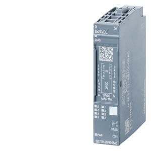
6ES7131-6BF00-0CA0
Eight-channel High Feature 24 V DC PNP input module with channel diagnostics, edge interrupts and pulse extension. Supports type A0 BaseUnits, MSI and isochronous operation.
Warranty coverage and terms are confirmed with your order.
We coordinate the fastest available shipping option for your destination.
Available payment methods are handled through secure payment channels.
Carrier and delivery options are confirmed for your destination before dispatch.
Independent supplier: Xindustra is not an authorized distributor, reseller, or representative of Siemens. Brand names are used for identification and compatibility purposes only. Read disclaimer
Signal characteristics, sensor wiring and configuration for the DI 8x24VDC HF.
The High Feature eight-channel input module adds channel-level wire-break and sensor-supply diagnostics, hardware interrupts, edge evaluation and pulse extension to ordinary 24 V DC signal acquisition. It also supports MSI and isochronous operation.
8
Sinking input for PNP signals (P-reading)
Type 3
24 V DC
−30 to +5 V
Referenced to M
+11 to +30 V
Referenced to M
2.5 mA
0.05 / 0.1 / 0.4 / 0.8 / 1.6 / 3.2 / 12.8 / 20 ms
Additional line-length-dependent delay: 30–500 µs
1.5 mA
1000 m
600 m
Dedicated red channel fault LEDs and channel-by-channel diagnostic messages identify the affected signal path. These are useful when stopping at a module-wide fault indication is not enough, or when an input transition must generate a hardware interrupt.
Rising edge, falling edge or edge change
50 / 100 / 200 / 500 ms; 1 / 2 s
Configurable on channels 0–7
Supported
Not supported
Input filtering, pulse extension and edge interrupts serve different purposes: filtering rejects short disturbances, pulse extension holds a detected signal longer, and an edge interrupt notifies the controller of a configured transition. Choose the filter before relying on an event signal; this module is not a dedicated counter or oversampling module.
| Parameter / condition | BaseUnit arrangement |
|---|---|
| 1-wire | BU type A0 |
| 2-wire | BU type A0 |
| 3-wire | BU type A0 with AUX terminals, or a potential distributor module |
| 4-wire | BU type A0 plus a potential distributor module |
Sensor supplies are electronically protected per channel. The maximum remains 700 mA for the whole module as well as for an individual channel; distributing sensors across eight terminals does not increase that total.
A light-colored BaseUnit starts a new potential group; a dark-colored BaseUnit continues the voltage buses from the module on its left. Select the module’s potential-group parameter to match the physical BaseUnit arrangement. The electronic module and BaseUnit are separate order items.
One- and two-wire sensor wiring
12/2017 · A5E03576305-AE, Figure 3-1. Original wiring and block diagram, including terminal numbers, voltage buses and the complete legend.
24 V DC
Permissible range: 19.2–28.8 V DC
Yes
39 mA
1.5 W
At 24 V with all 8 inputs supplied via the sensor supply
8
19.2 V
700 mA
Per channel and per module; total supply budget is 700 mA
Electronic, per channel
No
Yes
Supported
Supported, channel-by-channel
Supported, channel-by-channel
Yes, red
Green
Green PWR LED
Green/red DIAG LED
When wire-break diagnostics are enabled, place a 25–45 kΩ resistor in parallel with each mechanical contact to provide monitoring current while the contact is open. With wire-break detection disabled, this resistor is not required.
| Parameter / condition | Supported version / integration |
|---|---|
| STEP 7 TIA Portal | V13 SP1 |
| STEP 7 Classic | V5.5 |
| PCS 7 | V8.1 SP1 |
| PCS neo | V1.0.0 |
| PROFINET | GSDML V2.3 |
| PROFIBUS | Separate GSD files, revisions 3 and 5 or later |
1 byte plus 1 byte for QI
Supported
Supported
500 µs
420 µs
8 µs
4
Suitable for operation
I&M0 to I&M3
Not supported
Configure this exact ET 200SP module rather than a visually similar input module. Use the listed engineering-system support for the selected configuration path.
15 × 73 × 58 mm
Electronic module; excludes BaseUnit and packaging
28 g
−30 to +60 °C
Operation below 0 °C requires hardware status FS07 or later
−30 to +50 °C
Operation below 0 °C requires hardware status FS07 or later
5000 m
Above 2000 m, additional installation restrictions apply as described in the ET 200SP system manual
CC01
Type A
1 module
6ES7131-6BF00-0CA0 identifies the DI 8x24VDC HF electronic module in a one-piece packing unit. Order the type A0 BaseUnit separately for the intended wiring arrangement. This is a standard digital I/O module, not a fail-safe I/O module, interface module or complete ET 200SP station.
Manufacturer data and installation resources for this exact module.
Order the exact product and condition your project requires, with assistance from quotation through delivery.
Your quotation references the complete manufacturer part number to keep the requested product clear.
Tell us whether you need new original, new surplus, used, refurbished or repaired equipment.
Shipping options are prepared around your destination, quantity and requested delivery date.
Access available manufacturer product data, manuals and certificates associated with the order number.