
Exact product identification
Your quotation references the complete manufacturer part number to keep the requested product clear.
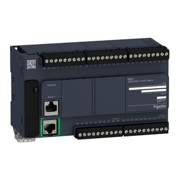
TM221CE40T
A 40-point Ethernet controller for dense 24 V DC I/O, with twenty-four digital inputs and sixteen sourcing PNP outputs. Two output-power groups and two fast channels support machine switching and pulse control.
Warranty coverage and terms are confirmed with your order.
We coordinate the fastest available shipping option for your destination.
Available payment methods are handled through secure payment channels.
Carrier and delivery options are confirmed for your destination before dispatch.
Independent supplier: Xindustra is not an authorized distributor, reseller, or representative of Schneider Electric. Brand names are used for identification and compatibility purposes only. Read disclaimer
I/O, PNP output wiring, communication and installation details for TM221CE40T.
The 40-point PNP base combines twenty-four inputs with fourteen regular outputs and two fast outputs. The two eight-channel output groups need their own V+/V− connections; adding channel count does not create one shared internal power bus.
TM221CE40T
Schneider Electric
Modicon M221
Compact
40
Digital inputs plus digital outputs; analog inputs are additional
24
16
2 × 0–10 V DC
24 V DC
20.4–28.8 V DC operating range
Removable screw terminal blocks
The T suffix identifies sourcing transistor outputs. It uses 24 V DC power and provides fast output functions that the relay variant does not offer.
There are 24 digital inputs in total, not 24 regular inputs plus four more. Four of those channels—I0, I1, I6 and I7—can be assigned to high-speed counting at up to 100 kHz. The remaining 20 channels are regular digital inputs. Choose the configured counting mode and input filter for the actual signal.
24 V DC; IEC/EN 61131-2 Type 1; sink/source
19.2–28.8 V DC
I0, I1, I6, I7
Shielded; maximum 10 m
Unshielded; maximum 30 m
2 single-ended voltage inputs
0–10 V DC
10 bits
±1% of full scale
Not isolated from internal logic; negative poles connected internally
Dedicated supplied cables; 1 m
The two built-in analog channels accept 0–10 V voltage signals. Use an appropriate analog expansion module for current-loop measurement rather than treating the onboard connector as a native 4–20 mA input.
These PNP outputs source current to 24 V DC loads. Apply the per-channel limit and the group-current budget together. Electronic short-circuit protection does not remove the need for correctly protected output power and wiring.
PNP sourcing transistor
16
0.5 A
24 V DC rated; 19.2–28.8 V DC range
4 A for Q0–Q7; 4 A for Q8–Q15
Q0 and Q1; up to 100 kHz
Electronic protection
Up to 100 Hz with resistive loads
PLS / PWM / PTO / FREQGEN
The output-current budget is subject to the hardware guide’s ambient-temperature and output-voltage derating curves. Do not apply the highest operating temperature and full simultaneous-on loading as independent maxima. Fast output wiring must be shielded and no longer than 3 m.
TM221CE40T output wiring
M221 hardware guide EIO0000003313.04, page 174. Output supply terminals, load-current path and shielded wiring for Q0/Q1.
1 × RJ45; Modbus TCP/IP; 10/100 Mbit/s
1 × RJ45; RS-232 / RS-485
USB 2.0 Mini-B
SD card slot
Physical switch and configurable input control
| Parameter / condition | Connection / equipment | Supported configuration |
|---|---|---|
| Local I/O | TM3 or TM2 expansion bus | Up to 7 expansion modules |
| Remote I/O | TM3 transmitter / receiver pair | Up to 7 additional TM3 modules |
| Distributed I/O | TM3 bus coupler over the appropriate network | Separate bus-coupler configuration |
The permitted configuration also depends on expansion-bus power consumption. TM3 transmitter/receiver modules do not count toward the seven expansion-I/O-module limit.
This 40-point compact controller provides two cartridge slots for supported TMC2 options. A cartridge is optional, not part of the 24 digital-input / 16 output count. TM3 expansion modules and TMC2 cartridges are separate order items.
Use EcoStruxure Machine Expert – Basic for M221 application programming, hardware configuration and diagnostics. It is the Basic edition for this controller range, not the separate Machine Expert environment used for M241/M251 projects. USB Mini-B provides a local programming connection; this Ethernet model also has a network interface.
512 kbytes
256 kbytes
256 kbytes
256 kbytes
Configured in Machine Expert – Basic
| Parameter / condition | Horizontal mounting | Vertical mounting |
|---|---|---|
| Ambient operating temperature | −10 to +55 °C | −10 to +35 °C |
| Expansion-module position | Beside the controller | Above the controller |
IP20 with protective covers fitted
DIN rail or panel
−25 to +70 °C
10–95%; noncondensing
0–2000 m
Pollution degree 2; enclosed industrial cabinet
Install the controller in an enclosure and maintain the mounting clearances in the hardware guide. Route power wiring separately from analog, communication and fast-I/O cables; shield the latter and terminate their shields at the grounding arrangement. M221 is a standard logic controller, not a safety controller.
Manufacturer resources for controller selection, wiring and programming.
Order the exact product and condition your project requires, with assistance from quotation through delivery.
Your quotation references the complete manufacturer part number to keep the requested product clear.
Tell us whether you need new original, new surplus, used, refurbished or repaired equipment.
Shipping options are prepared around your destination, quantity and requested delivery date.
Access available manufacturer product data, manuals and certificates associated with the order number.