
Exact product identification
Your quotation references the complete manufacturer part number to keep the requested product clear.
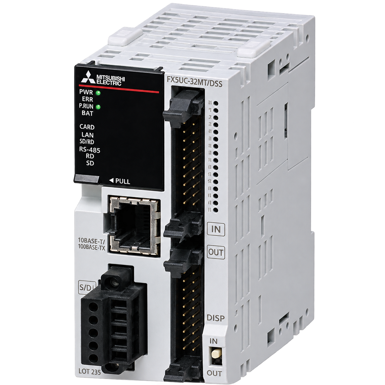
FX5UC-32MT/D
Compact connector-type FX5UC PLC CPU with 16 digital inputs and 16 sink transistor outputs. 24 V DC supply, built-in Ethernet and RS-485, 42.1 mm body width.
Warranty coverage and terms are confirmed with your order.
We coordinate the fastest available shipping option for your destination.
Available payment methods are handled through secure payment channels.
Carrier and delivery options are confirmed for your destination before dispatch.
Independent supplier: Xindustra is not an authorized distributor, reseller, or representative of Mitsubishi Electric. Brand names are used for identification and compatibility purposes only. Read disclaimer
CPU capacity, field wiring and installation requirements for FX5UC-32MT/D.
FX5UC-32MT/D
16 inputs + 16 transistor outputs
Connector type
Sink
Transistor sink
MELSOFT GX Works3
64k steps; up to128k steps with supported firmware/tool
10/100 Mbps, RJ45
RS-485/RS-422, up to115.2 kbps, non-isolated
Firmware1.100 and GX Works3 1.047Z or later support128k program steps and up to384 local I/O points; earlier versions use64k steps and up to256 local I/O. Local and remote I/O together remain within512 points. Memory capacity is distinct from scan time and the number of physical terminals.
Ethernet supports MELSOFT connections, SLMP, socket communication and MODBUS/TCP among the documented functions. The built-in serial interface supports MODBUS RTU and other listed protocols; configure protocol parameters and the terminal resistor for the connected network. Ethernet availability alone does not mean that an EtherNet/IP interface is built in.
The /D version uses sink input wiring for no-voltage contacts or NPN open-collector devices and sink-type transistor outputs. Its field circuit differs from the /DSS source-output version even when the total I/O count is the same.
24 V DC, +20% / −15%
5–30 V DC
0.3 A per point
0.1 A per point
0.8 A per common for8 output points
≤0.1 mA at30 V DC
≤1.0 V
≤1.5 V
Hardware manual p.33. Use sink wiring for /D and source wiring for /DSS. Common-group and per-point limits both apply.
The high-speed input group is X0–X5, with200 kHz response under the specified pulse conditions. The remaining input groups have lower response frequencies. Y0–Y3 have faster switching characteristics than later outputs; do not apply the fast-channel ratings to every terminal.
24 V DC, +20% / −15%
5 W at24 V DC
42.1 ×90 ×89.1 mm
Inside a control panel, DIN rail mounting
−20 to +55 °C, non-freezing; low-temperature and revision conditions apply
5–95% RH, noncondensing
The CPU-only wattage does not include the complete extension configuration or external field loads. The CPU’s internal supply capacities are720 mA at5 V and500 mA at24 V; calculate extension consumption and any required extension power supply for the selected modules.
Hardware manual p.38: use the 42.1 mm width row. The32/64/96-point bodies have different widths; leave room for I/O cables and extensions.
Hardware manual p.34. Only the lower I/O derating graph applies to these transistor CPUs; the upper relay table describes a different model.
Permitted simultaneous input/output ON ratios depend on ambient temperature and whether extension modules are connected. The -20 °C lower endpoint applies to products manufactured from June2016; earlier products have a0 °C lower endpoint. For operation below0 °C, use the manual’s low-temperature precautions. Provide external protective circuits for inductive loads and output short circuits.
Order the exact product and condition your project requires, with assistance from quotation through delivery.
Your quotation references the complete manufacturer part number to keep the requested product clear.
Tell us whether you need new original, new surplus, used, refurbished or repaired equipment.
Shipping options are prepared around your destination, quantity and requested delivery date.
Access available manufacturer product data, manuals and certificates associated with the order number.